Step 1: SAFETY INFORMATION
The following symbols and/or signal words may be used in this document:
Indicates a hazardous situation which, if not avoided, will result in death or serious injury.
Indicates a hazardous situation which, if not avoided, could result in death or serious injury.
Indicates a hazardous situation which, if not avoided, could result in minor or moderate personal injury.
Indicates an instruction which, if not followed, could severely damage engine components or other property.
These safety alert signal words mean:
ATTENTION!
BECOME ALERT!
YOUR SAFETY IS INVOLVED!
For safety reasons, this kit must be installed by an authorized Evinrude dealer. This instruction sheet is not a substitute for work experience. Additional helpful information may be found in other service literature.
DO NOT perform any work until you have read and understood these instructions completely. Torque wrench tightening specifications must strictly be adhered to.
Should removal of any locking fastener (lock tabs, locknuts, or patch screws) be required, always replace with a new one.
When replacement parts are required, use Evinrude/Johnson® Genuine Parts or parts with equivalent characteristics, including type, strength and material. Use of substandard parts could result in injury or product malfunction.
Always wear EYE PROTECTION AND APPROPRIATE GLOVES when using power tools.
Unless otherwise specified, engine must be OFF (not running) when performing this work.
Always be aware of parts that can move, such as flywheels, propellers, etc.
Some components may be HOT. Always wait for engine to cool down before performing work.
If you use procedures or service tools that are not recommended in this instruction sheet, YOU ALONE must decide if your actions might injure people or damage the outboard.
This instruction sheet may be translated into other languages. In the event of any discrepancy, the English version shall prevail.
TO THE INSTALLER: Give this sheet and the operating instructions to the owner. Advise the owner of any special operation or maintenance information contained in the instructions.
TO THE OWNER: Save these instructions in your owner’s kit. This sheet contains important information for the use and maintenance of your engine.
Step 2: ACCESSORY POWER INPUT HARNESS KITS P/N’s 766592, 766593, 766594, 766595
Use this accessory power input harness for all ICON II network applications.

| Ref | P/N | Name of Part | Qty |
|---|---|---|---|
| – | 766594 | ACCESSORY POWER INPUT HARNESS, 5 ft. (1.52 M) | 1 |
| – | 766595 | ACCESSORY POWER INPUT HARNESS, 10 ft. (3.04 M) | 1 |
| – | 766592 | ACCESSORY POWER INPUT HARNESS, 15 ft. (4.57 M) | 1 |
| – | 766593 | ACCESSORY POWER INPUT HARNESS, 25 ft. (7.62 M) | 1 |
Step 3: INSTALLATION
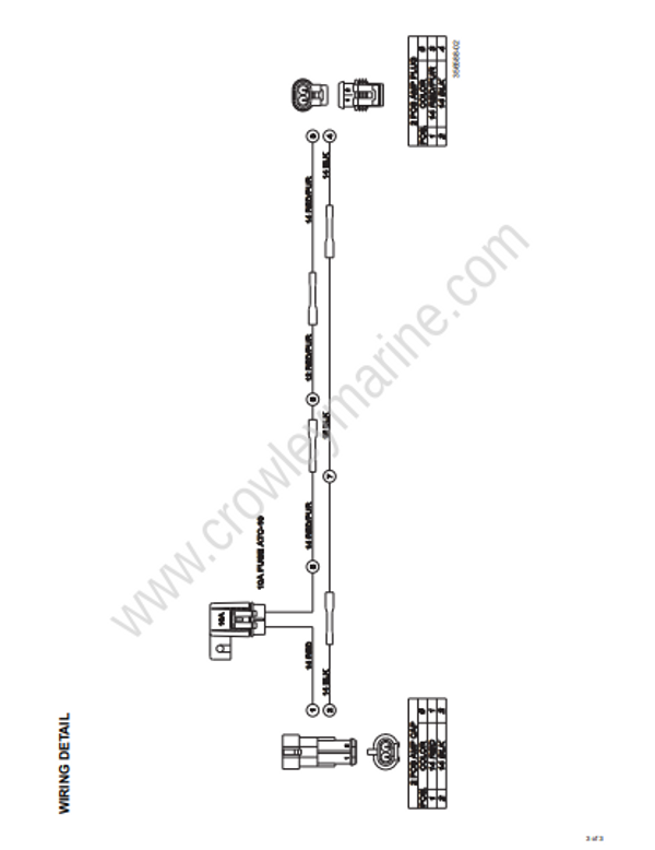
Visually inspect the 10A fuse.
Connect the 2-position cap to the battery cable.
Connect the 2-position plug to the accessory power input connector on the remote control wiring harness.
Step 4: SAFETY INFORMATION
The following symbols and/or signal words may be used in this document:
Indicates a hazardous situation which, if not avoided, will result in death or serious injury.
Indicates a hazardous situation which, if not avoided, could result in death or serious injury.
Indicates a hazardous situation which, if not avoided, could result in minor or moderate personal injury.
Indicates an instruction which, if not followed, could severely damage engine components or other property.
These safety alert signal words mean:
ATTENTION!
BECOME ALERT!
YOUR SAFETY IS INVOLVED!
For safety reasons, this kit must be installed by an authorized Evinrude dealer. This instruction sheet is not a substitute for work experience. Additional helpful information may be found in other service literature.
DO NOT perform any work until you have read and understood these instructions completely.
Torque wrench tightening specifications must strictly be adhered to.
Should removal of any locking fastener (lock tabs, locknuts, or patch screws) be required, always replace with a new one.
When replacement parts are required, use Evinrude/Johnson® Genuine Parts or parts with equivalent characteristics, including type, strength and material. Use of substandard parts could result in injury or product malfunction.
Always wear EYE PROTECTION AND APPROPRIATE GLOVES when using power tools.
Unless otherwise specified, engine must be OFF (not running) when performing this work.
Always be aware of parts that can move, such as flywheels, propellers, etc.
Some components may be HOT. Always wait for engine to cool down before performing work.
If you use procedures or service tools that are not recommended in this instruction sheet, YOU ALONE must decide if your actions might injure people or damage the outboard.
This instruction sheet may be translated into other languages. In the event of any discrepancy, the English version shall prevail.
TO THE INSTALLER: Give this sheet and the operating instructions to the owner. Advise the owner of any special operation or maintenance information contained in the instructions.
TO THE OWNER: Save these instructions in your owner’s kit. This sheet contains important information for the use and maintenance of your engine.
Step 5: ACCESSORY POWER INPUT HARNESS KITS P/N’s 766592, 766593, 766594, 766595
Use this accessory power input harness for all ICON II network applications.

| Ref | P/N | Name of Part | Qty |
|---|---|---|---|
| – | 766594 | ACCESSORY POWER INPUT HARNESS, 5 ft. (1.52 M) | 1 |
| – | 766595 | ACCESSORY POWER INPUT HARNESS, 10 ft. (3.04 M) | 1 |
| – | 766592 | ACCESSORY POWER INPUT HARNESS, 15 ft. (4.57 M) | 1 |
| – | 766593 | ACCESSORY POWER INPUT HARNESS, 25 ft. (7.62 M) | 1 |
Step 6: INSTALLATION
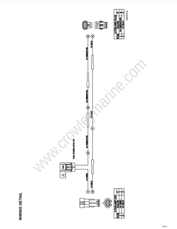
Visually inspect the 10A fuse.
Connect the 2-position cap to the battery cable.
Connect the 2-position plug to the accessory power input connector on the remote control wiring harness.