

Preface
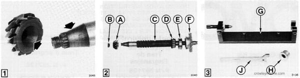
This kit is used for 1975 - CO, 40-60 models. The forward gear and pinion are factory-matched. Do not use either gear separately.
1. Read complete instruction prior to starting work.
[1]
2. Remove original shims and thoroughly clean all parts. Degrease pinion and drive shaft tapers.
[2]
3. Assemble pinion (A) and pinion nut (B) to driveshaft (C), tighten nut to a torque of 54-60 Nm (40-45 ft. lbs.). Assemble bearing (D), cone (E), and driveshaft seal housing (F) onto driveshaft.
[3]
4. With this matched gearset, you must use Universal Shim Gauge, P/N 0393185 (G).
Use Collar, P/N 0328361 (H).
Use Shim Gauge Bar, P/N 328365 (J).
Do not use Shim Gauge Bar, P/N 0328364 or Shim Gauge Tool, P/N 0320739 as indicated in previous service manuals.

[4]
5. Slide collar (H) onto the driveshaft with the flanged end (K) contacting the seal housing (F).
5 [6] [7]
6. Insert driveshaft assembly (L) into tool base ** (M). Tighten screw **(N) against driveshaft center until spring loaded plunger is compressed to groove (O). Tighten jam nut.
7. Rotate driveshaft assembly several revolutions to seat bearings.
[8]
8. Position Shim Gauge Bar, P/N 0328365 (J), against guide pins (P) of the tool base (M).
[9] [10]
9. Hold shim gauge bar (J) against pinion. Rotate seal housing, and measure clearance at each screw hole flange and between each pair of screw holes. If variance exceeds 0.050 mm (0.002 in.) between screw hole flange and each pair of screw holes, replace seal housing and recheck.
[11]
10. Hold shim gauge bar (J) between screw holes of seal housing. Rotate driveshaft and pinion assembly and measure clearance between the shim gauge bar and pinion (A). If variance exceeds 0.050 mm (0.002 in.), replace driveshaft or gearset and recheck.
11. Subtract final clearance measurement from 0.508 mm (0.020 in.) to determine required shim thickness.
12. Remove driveshaft assembly from tool base.
Use extreme care when removing seal housing from driveshaft to avoid damaging the seals.
13. Remove collar and seal housing from driveshaft and install the required amount of shims.
[12]
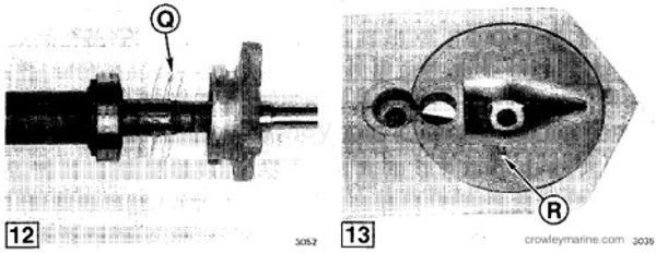
14. Reassemble driveshaft with required thickness of shims (Q). Slide collar onto driveshaft and place assembly back into tool base.
15. The measurement between the shim gauge bar and pinion should be 0.508 mm (0.020 in.).
16. Remove driveshaft assembly from tool base. Remove collar, nut and pinion from driveshaft.
[13]
17. To identify gearcase for future service, stamp an "M" on the gearcase in the trim tab area (R).