

Carburetor
Carburetor
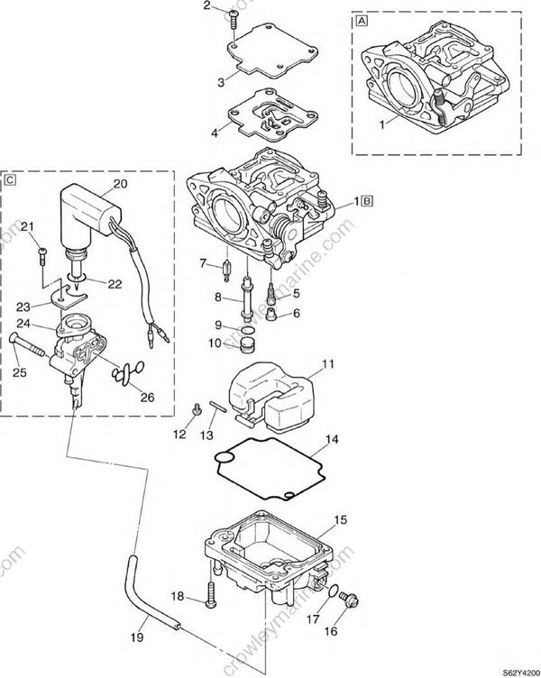
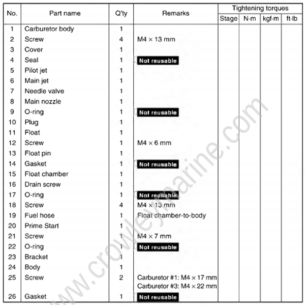
[a] Carburetors #1, #2, and #3
[b] Carburetor #4
[c] Carburetors #1 and #3
Disassembling the carburetor
Before disassembling the carburetor, make sure to note the number of times the pilot screw is turned out from the seated position to its set position.
Checking the carburetor
Check the air and fuel passages and jets, for dirt and foreign matter. Clean the car buretor body with a petroleum based sol vent if necessary.
Blow compressed air into all passages and jets.
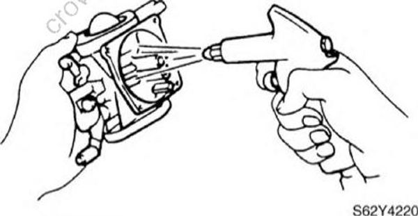
• Direct the compressed air downward,otherwise cleaning solvent may be
blown into your eyes or small parts of the carburetor may be blown off.
• Do not use steel wire for cleaning the jets, otherwise the jet diameters may be enlarged, which may seriously affect performance.
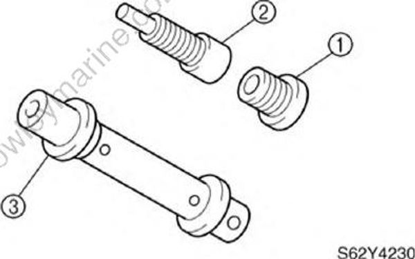
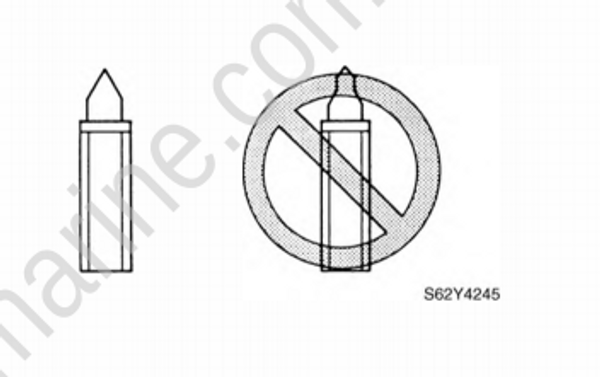
- Check the main jet (1), pilot jet (2), and main nozzle (3) for dirt or residue. Clean if necessary.
- Check the needle valve for bends or wear. Replace if necessary.
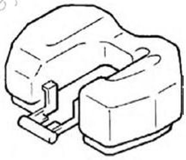
- Check the float for deterioration. Replace it necessary.
- Measure the float height (a). Replace the float and needle valve, if out of specification, as a set.
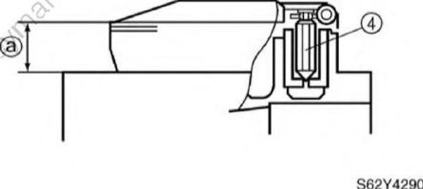
• The float should be resting on the needle valve (4), but not compressing it.
• Take measurements at the top of the float flange opposite its pivoted side.
Float height (a): 10.0 ± 0.5 mm (0.39 ± 0.02 in)
Checking the Prime Start
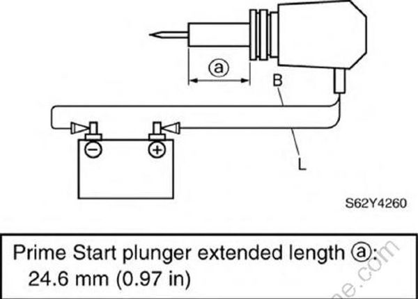
Measure the length of the Prime Start plunger.
Connect the positive Prime Start blue (L) lead and the negative Prime Start black (B) lead to a battery as shown.
Measure the plunger length (a) after applying power for 5 minutes. Replace if out of specification.
Assembling the carburetor
Before assembling the carburetor, make sure to turn the pilot screw the same number of times, as noted before disassembly, from the seated position to the set position.
- Install the main nozzle (T), plug pilot jet (3), and main jet (4) to the carburetor body as shown.
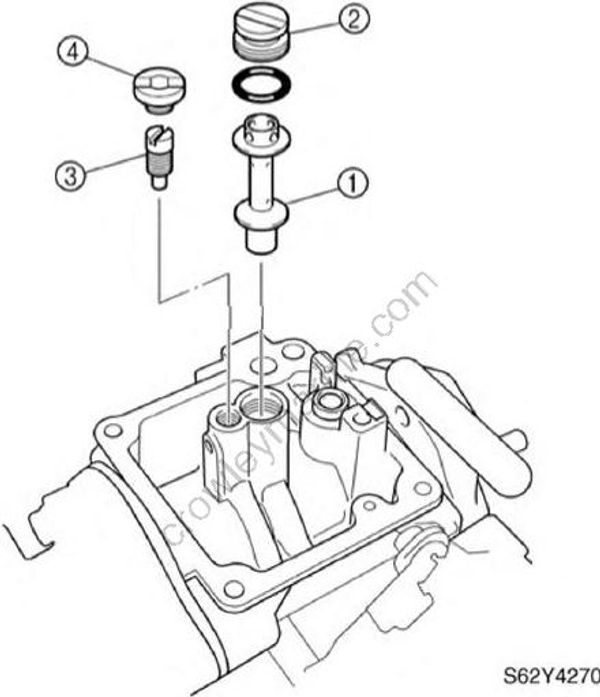
- Install the needle valve (5), float (6), float pin (7), and screw (8) as shown, and then the check the float for smooth operation.
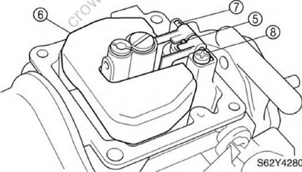
• Place the needle valve in the valve seat when installing the float to the carburetor body.
• Fit the float pin into the slit on the carbure tor body and lock it with the screw.
Adjusting the throttle link rod
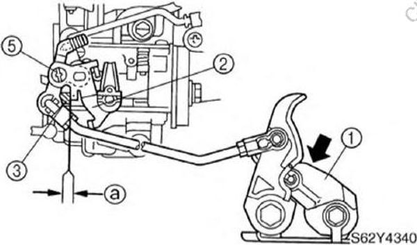
Push the throttle control lever (1) to the fully open position as shown, and then measure the gap between the carburetor throttle lever (2) and carburetor stopper (3).
If out of specification, adjust the throttle link rod length.
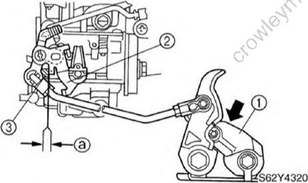
Gap (a): Less than 0.5 mm (0.02 in)
- Remove the throttle link rod (4), adjust it to the specified length (b), and then install it.
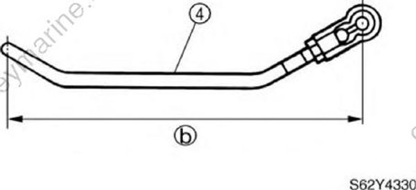
Throttle link rod length (b): 144 mm (5.67 in)
Push the throttle control lever (1) to the fully open position as shown.
While pushing the carburetor throttle lever (2) against the carburetor stopper (3), loosen, and then tighten the adjusting screw (5).
Synchronizing the carburetors
Start the engine and warm it up for 5 minutes to check the stability of the engine.
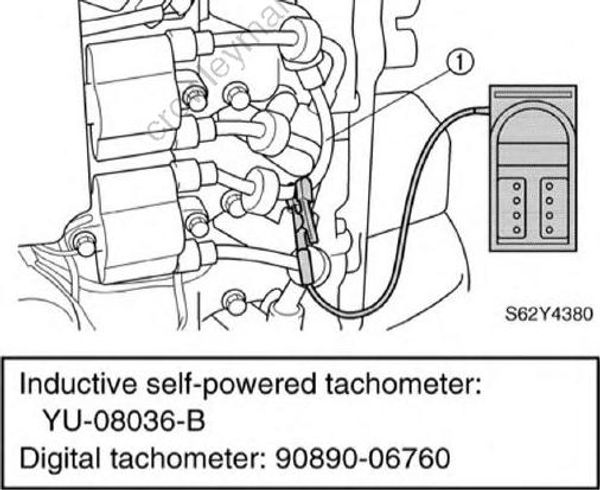
Attach the special service tool to the high-tension cord #1 (1).
- Remove all of the plugs (2) and attach the special service tool and adapters to the carburetor assembly as shown.
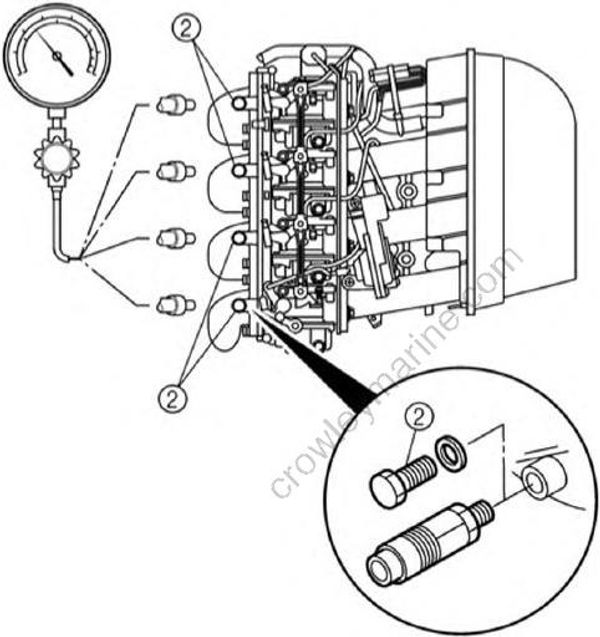
Carburetor synchronizer: YU-08030 Vacuum gauge: 90890-03159
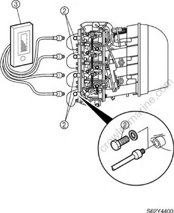
For best results, use a vacuum gauge (3) (commercially obtainable) with four adapters like the one shown in the illustration.
- Adjust the idle speed to 1,000 r/min by turning the throttle stop screw (4) on carburetor #4 in direction (a) or (b).
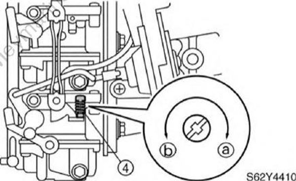
• To increase idle speed, turn the throttle stop screw in direction (a).
• To decrease idle speed, turn the throttle stop screw in direction ®.
Measure the vacuum pressure of carburetor #4.
Turn the throttle valve adjusting screws (5) to adjust the vacuum pressure of carburetors #1, #2, and #3 to the same vac uum variation as carburetor #4.
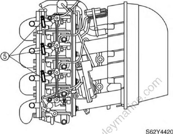
- Adjust the engine idle speed to specification.
Engine idle speed:
F50: 850 ± 50 r/min
T50: 950 ± 50 r/min
- After adjusting the idle speed, rev the engine a few times and let it idle for at least 15 seconds to check that the vacuum pressures stay within 50 mm Hg (67 m bar, 1.97 in Hg) and to check the stability of the engine.
Adjusting the dash-pot (acceleration pump)
Start the engine and warm it up for 5 minutes, and then check the engine speed at the operation point of the dash-pot.
Attach the special service tool to high tension cord #1 (1).
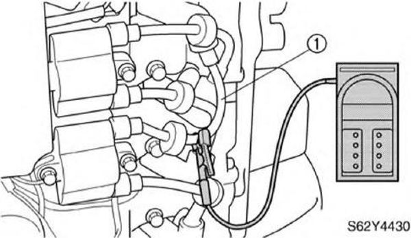
Inductive self-powered tachometer: YU-08036-B
Digital tachometer: 90890-06760
- Open the throttle cam (2) slowly, and check the engine speed when the
acceleration pump stopper (3) comes into contact with point (a).
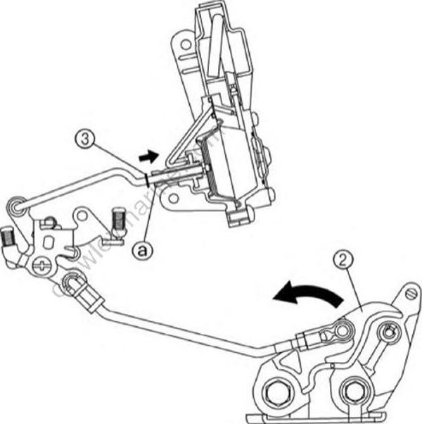
Engine speed: 2,700 r/min
If out of specification, adjust the engine speed at the operation point of dash-pot.
Open the throttle cam (2) slowly, and check that the acceleration pump stopper (3) comes in contact with point (a).
Turn the adjusting screw (4) in or out until the specified engine speed is obtained.
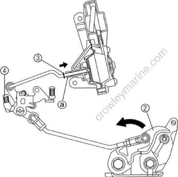
- Open and close the throttle cam a few times, and check the engine speed at the operation point of dash-pot again. Adjust if necessary.
