

EXPLODED DIAGRAM
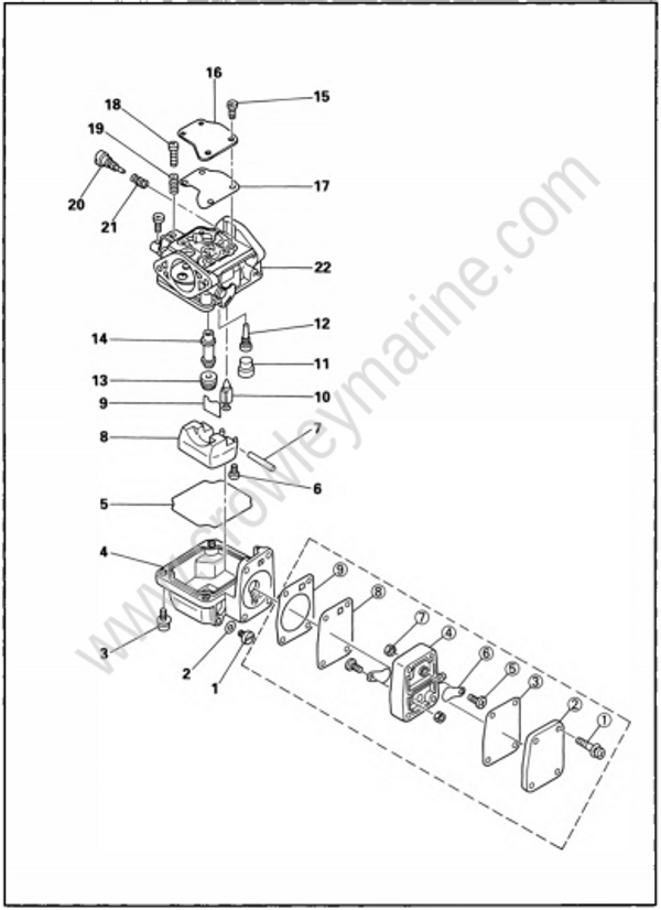
REMOVAL AND INSTALLATION CHART
| Step | Procedure/Part name | Q'ty | Service points |
|---|---|---|---|
| CARBURETOR DISASSEMBLY | Follow the left "Step" for removal | ||
| Carburetor assembly | Refer to the "CARBURETOR REMOVAL"section in chapter 4. | ||
| 1 | Drain screw | 1 | |
| 2 | Washer | 1 | |
| 3 | Screw (with washer) | 4 | 4x14 mm |
| 4 | Float chamber | 1 | |
| 5 | Float chamber packing | 1 | |
| 6 | Screw | 1 | |
| 7 | Arm pin | 1 | |
| 8 | Float | 1 | |
| 9 | Clip | 1 | |
| 10 | Needle valve | 1 | |
| 11 | Cap | 1 | |
| 12 | Pilot jet | 1 | |
| 13 | Main jet | 1 | |
| 14 | Main nozzle | 1 | |
| 15 | Screw (with washer) | 4 | 4 x 10 mm |
| 16 | Plate | 1 | |
| 17 | Packing | 1 | |
| 18 | Stopping screw | 1 | |
| 19 | Spring | 1 | |
| 20 | Pilot adjusting screw | 1 | |
| 21 | Spring | 1 | |
| 22 | Carburetor body | 1 | |
| FUEL PUMP DISASSEMBLY | |||
| (1) | Screw (with washer) | 4 | |
| (2) | Pump cover | 1 | |
| (3) | Diaphragm | 1 | |
| (4) | Pump body | 1 | |
| (5) | Screw | 2 | |
| (6) | Seat valve | 2 | |
| (7) | Nut | 2 | |
| (8) | Diaphragm | 1 | |
| (9) | Diaphragm gasket | 1 | |
| Reverse the removal steps for installation. |
SERVICE POINTS
NOTE:
Do not use steelwire for cleaning the jets as this may enlarge the jet diameters and seriously affect performance.
Carburetor inspection
- Inspect:
- Carburetor body
Crack/Damage ➝ Replace.
Contamination ➝ Clean
- Carburetor body
- Inspect:
- Pilot screw
Bend/Wear ➝ Replace.
- Pilot screw
- Inspect:
- Main jet
- Pilot jet
- Main nozzle
Contamination ➝ Replace
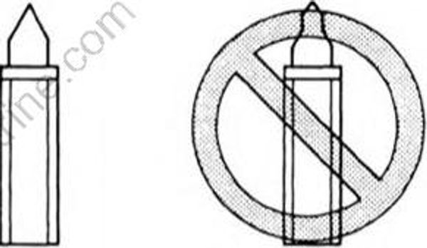
- Inspect:
- Needle valve
Grooved wear ➝ Replace.
- Needle valve
- Inspect:
- Float
Crack/Damage ➝ Replace.
- Float
Fuel pump inspection
- Inspect:
- Body
Crack/Leak/Damage ➝ Replace.
- Body
- Inspect:
- Seat valve
Crack/Distortion ➝ Replace.
- Seat valve
- Inspect:
• Diaphragm
Damage ➝ Replace.
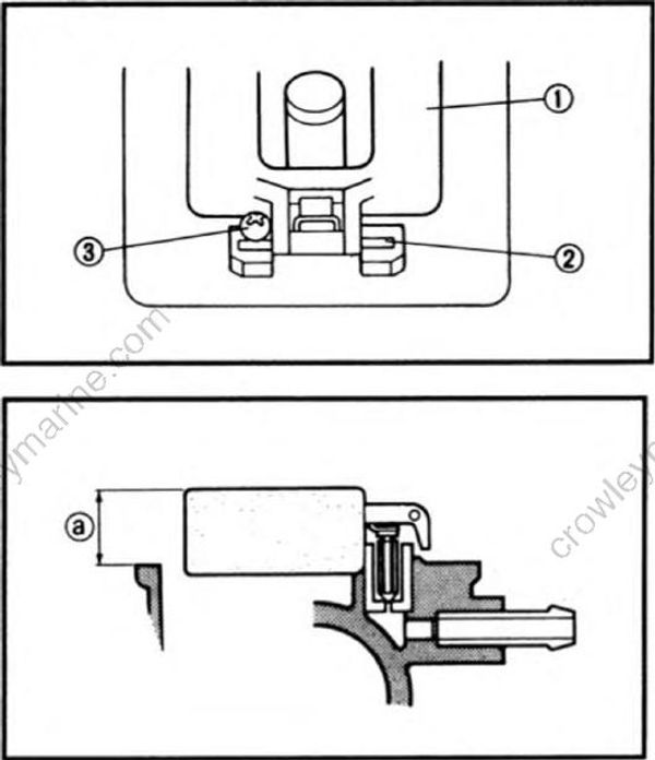
Carburetor assembly
- Install:
- Needle valve
- Float (1)
- Float pin (2)
- Screw (3)
NOTE:
- The float pin should be fit in the slit the carburetor and locked with the screw.
- After installing, check the smooth movement of the float.
- Measure:
- Float height (a)
Out of specification ➝ Replace.
- Float height (a)
Float height (a) : 14.0 ± 1.5 mm (0.55 ± 0.06 in)
NOTE:
- The float should be resting on the needle valve, but not compressing the needle valve.
- Take measurement at the end surface of the float opposite to its pivoted side.
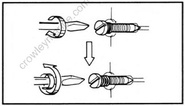
- Adjust:
- Pilot screw
Adjustment steps:
- Screw in the pilot screw until it is lightly seated.
- Back out by the specified number of turns.
Pilot screw : 1-1/2 ± 1/4 (turns out)
