

Choke solenoid
- Disconnect the choke solenoid leads from the choke solenoid and wire harness.
- Check the choke solenoid as specified using the pocket tester.
Continuity.................................Normal
Discontinuity.............................Defective
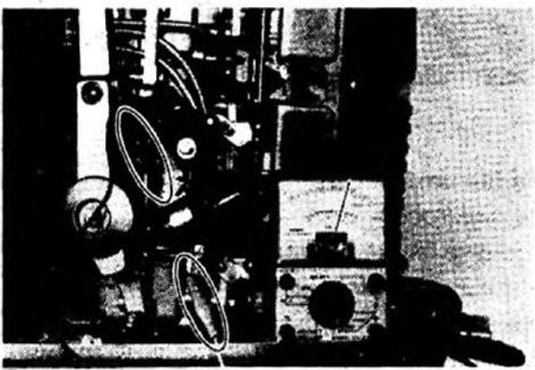
- If the element is broken, replace the entire unit.
Installation
Refer to page 4-41.
LOWER UNIT AND RELATED PARTS
Power trim and tilt motor
Removal
Refer to page 5-18.
Disassembly
- Loosen the wire harness bolt, and remove the two bolts securing the frame end.
- Remove the commutator end by tapping on it with a plastic hammer.
1. Remove the lead wire while taking care not to break it.
2. Spray WD-40 on the lead, so the frame can easily be removed.
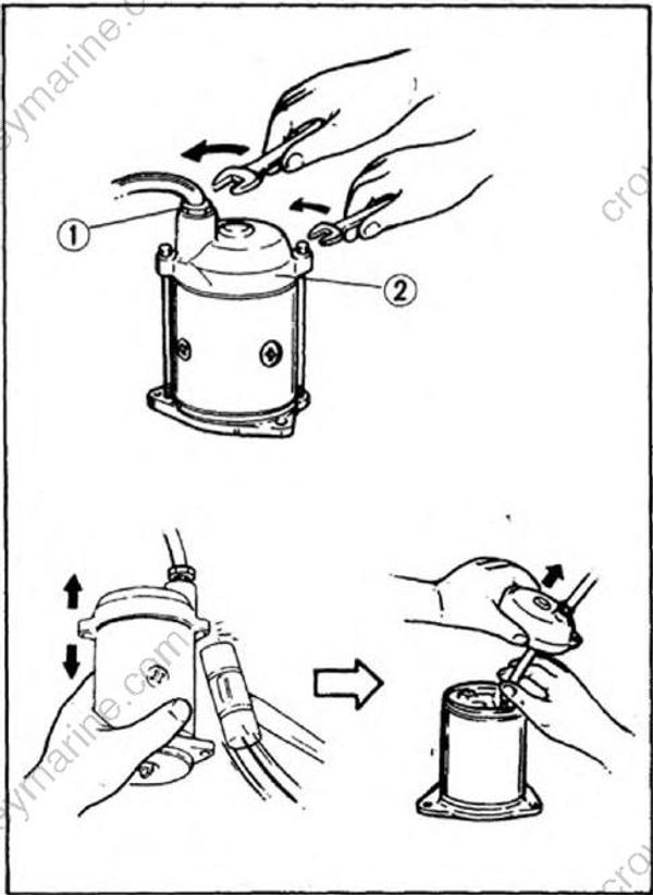
- Wire harness bolt
- Commutator end
- Remove the brushes from the brush holder, and by tapping the frame end with a plastic hammer, remove the frame end.
- Remove the armature from the frame end.
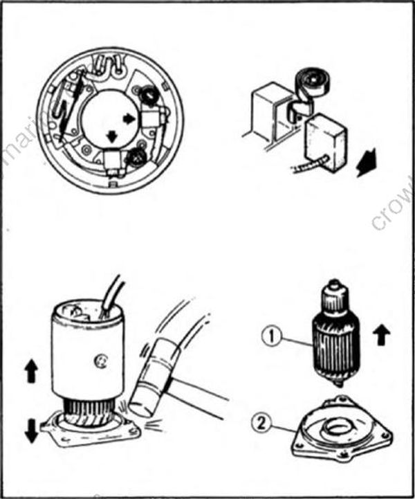
- Armature
- Frame end
INSPECTION AND REPAIR
Armature
- Check surfaces of the commutator. Using sandpaper (#500 or #600), smooth out any rough surface. If roughened excessively, turn the commutator in a lathe. If its run-out is 0.2 mm (0.008 in) or more, take the same step.
- Measure the commutator mica undercut. If the depth is 0.2 mm (0.008 in) or less, cut it to the specification.
Under cut: 0.4 ~ 0.8 mm (0.015 ~ 0.03 in)
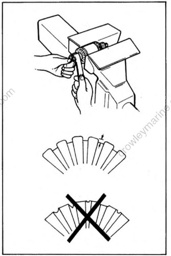
- Check continuity between the armature coil and ground.
If there is continuity, the armature coil is grounded and therefore, it should be replaced.
