

EXPLODED DIAGRAM
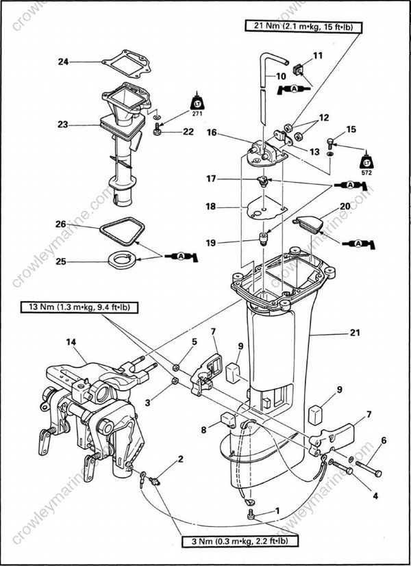
REMOVAL AND INSTALLATION CHART
| Step | Procedure/Part name | Q'ty | Service points |
|---|---|---|---|
| UPPER CASE REMOVAL | Follow the left "Step" for removal. | ||
| Bottom cowling assembly | Refer to the "BOTTOM COWLING REMOVAL" section. | ||
| Lower unit | Refer to the "LOWER UNIT REMOVAL" section in chapter 6. | ||
| 1 | Screw | 1 | |
| 2 | Nipple | 1 | |
| 3 | Nut | 2 | |
| 4 | Bolt (with washer) | 2 | 6 x 55 mm |
| 5 | Nut | 2 | |
| 6 | Bolt (with washer) | 2 | 6x75 mm |
| 7 | Lower mount rubber housing | 2 | |
| 8 | Front mount rubber | 1 | |
| 9 | Side mount rubber | 2 | |
| 10 | Water tube | 1 | |
| 11 | Seal rubber | 1 | |
| 12 | Nut | 2 | |
| 13 | Plate | 1 | |
| 14 | Bracket unit assembly | 1 | |
| 15 | Bolt (with washer) | 3 | 6 x 18 mm |
| 16 | Upper rubber mount | 1 | |
| 17 | Water rubber seal | 1 | |
| 18 | Upper casing gasket | 1 | |
| 19 | Water rubber seal | 1 | |
| 20 | Plane rubber | 1 | |
| 21 | Upper case | 1 | |
| EXHAUST MANIFOLD REMOVAL | |||
| Power unit | Refer to the "POWER UNIT REMOVAL" section in chapter 5 | ||
| 22 | Bolt (with washer) | 5 | 6 x 20 mm |
| 23 | Exhaust manifold | 1 | |
| 24 | Exhaust manifold gasket | 1 | |
| 25 | Exhaust manifold packing | 1 | |
| 26 | O-ring | 1 | |
| Reverse the removal steps for installation. |
SERVICE POINTS
Rubber mount inspection
- Inspect:
• Rubber mount
Wear/Crack/Damage ➝ Replace.
Mount bolt inspection
- Inspect:
• Mount bolt
Wear/Bent/Damage ➝ Replace.
