

EXPLODED DIAGRAM
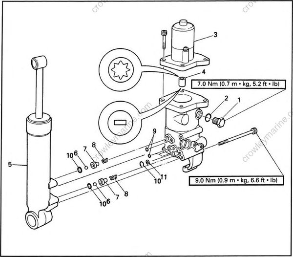
REMOVAL AND INSTALLATION CHART
| Step | Procedure/Part name | Q'ty | Service points |
|---|---|---|---|
| TILT CYLINDER, PUMP HOUSING, AND MOTOR REMOVAL | Follow the left "Step" for removal. | ||
| 1 | Reservoir plug | 1 | |
| 2 | O-ring | 1 | 8.8x 1.9 mm |
| 3 | PTT motor | 1 | |
| 4 | Connector shaft | 1 | |
| 5 | Tilt cylinder | 1 | |
| 6 | Ball | 2 | |
| 7 | Plunger | 2 | |
| 8 | Spring | 2 |
EXPLODED DIAGRAM
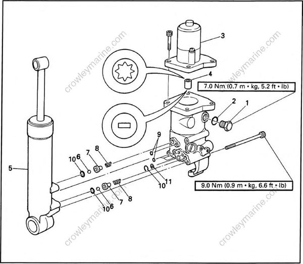
| Step | Procedure/Part name | Q'ty | Service points |
|---|---|---|---|
| 9 | O-ring | 4 | 5.5 x 1.5 mm |
| 10 | O-ring | 3 | 10.7 x 1.5 mm |
| 11 | Screen | 1 |
Reverse the removal steps for installation
SERVICE POINTS
• To prevent the hydraulic fluid from spurting out due to internal pressure, the outboard should be kept fully tilted up (the tilt rod at full length).
• After removing the tilt motor or oil reservoir, do not push the tilt rod down. This may cause hydraulic fluid to spurt out from the port.
Do not wipe hydraulic system components with rags, paper, tissues, or the like, as fibers from such material will cause malfunctions if they enter the system.
Removal of the tilt cylinder is not necessary for cylinder repair.
