

EXPLODED DIAGRAM
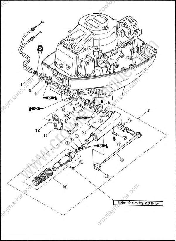
REMOVAL AND INSTALLATION CHART AND SHIFT LEVER
| Step | Procedure/Part name | Q'ty | Service points |
|---|---|---|---|
| 1 | STEERING HANDLE REMOVAL | Follow the left "Step" for removal. | |
| Control pulley bracket assembly | Refer to the "POWER UNIT REMOVAL" section in chapter 5. | ||
| 1 | Bolt | 1 | 6 x 16 mm |
| 2 | Plate | 1 | |
| 3 | Bushing | 1 | |
| 4 | Plane washer | 1 | |
| 5 | Wave washer | 1 | |
| 6 | Bushing | 1 | |
| 7 | Steering handle assembly | 1 | |
| SHIFT LEVER REMOVAL | |||
| 8 | Clip | 1 | |
| 9 | Plane washer | 1 | |
| 10 | Bolt | 1 | 6 x 12 mm |
| 11 | Shift lever | 1 | |
| 12 | Wave washer | 1 | |
| 13 | Shift link rod | 1 | |
| STEERING HANDLE DISASSEMBLY | |||
| (1) | Screw | 2 | |
| (2) | Plate | 1 | |
| (3) | Clip | 1 | |
| (4) | Friction adjusting screw | 1 | |
| (5) | Screw | 1 | |
| (6) | Steering grip | 1 | |
| (7) | Plane washer | 1 | |
| (8) | Spring | 1 | |
| (9) | Bushing | 1 | |
| (10) | Throttle shaft | 1 | |
| (11) | Friction piece | 1 | |
| (12) | Throttle cable | 2 | |
| Reverse the removal steps for installation. |
SERVICE POINTS
Control cable inspection
- Inspect:
- Throttle cable
Kink/Fray/Stick → Replace.
- Throttle cable
Bushing inspection
- Inspect:
- Bushing
Wear/Crack/Damage → Replace.
- Bushing
Friction piece inspection
- Inspect:
- Friction piece
Wear/Crack/Damage → Replace.
- Friction piece
Steering handle inspection
- Inspect:
- Steering handle
Wear/Crack/Damage → Replace.
- Steering handle
Throttle shaft inspection
- Inspect:
- Throttle shaft
Wear/Bent/Damage → Replace.
- Throttle shaft
