

EXPLODED DIAGRAM
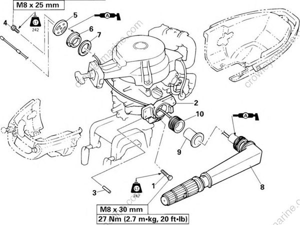
REMOVAL AND INSTALLATION CHART
| Step | Procedure/Part name | Q'ty | Service points |
|---|---|---|---|
| STEERING HANDLE REMOVAL | Follow the left "Step" for removal | ||
| Carrying handle 2 (protector) | |||
| Bottom cowling 2 | |||
| Carrying handle 1 | |||
| Engine stop switch lead | NOTE: Disconnect from the power unit side. | ||
| Choke wire | |||
| Throttle cable | |||
| Bottom cowling 1 | |||
| 1 | Bolt (steering bracket) | 2 | |
| 2 | Steering bracket | 1 | |
| 3 | Dowel pin | 1 |
EXPLODED DIAGRAM
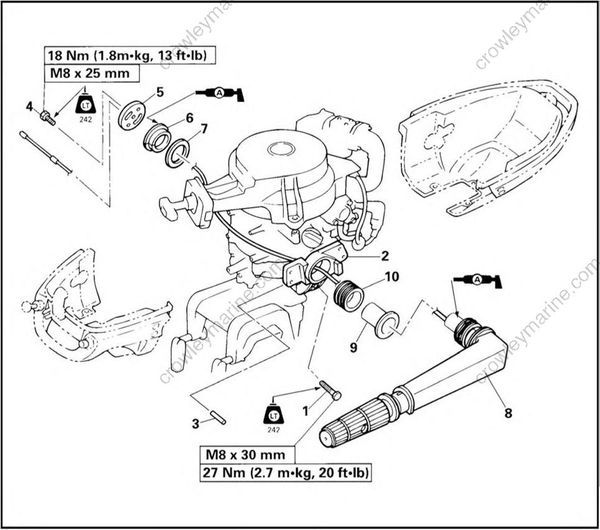
| Step | Procedure/Part name | Q'ty | Service points |
|---|---|---|---|
| 4 | Bolt (steering handle ass'y) | 1 | |
| 5 | Steering handle cover | 1 | |
| 6 | Collar | 1 | |
| 7 | Plate washer | 1 | |
| 8 | Steering handle ass'y | 1 | |
| 9 | Collar | 1 | |
| 10 | Rubber bushing | 1 | |
| Reverse the removal steps for installation. |
SERVICE POINTS
Rubber bushing installation
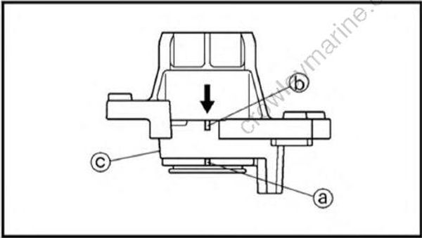
- Install:
• Rubber bushing
• Align the projection (a) on the pressure fit side of the rubber bushing flange with the projection (b) on the steering bracket.
• Push the rubber bushing on its inner cylinder in the direction of the arrow as shown and pressure fit it into the steering bracket.
• After fitting it, check that there is no clearance between the bushing flange and the steering bracket end (c).
Throttle cable installation
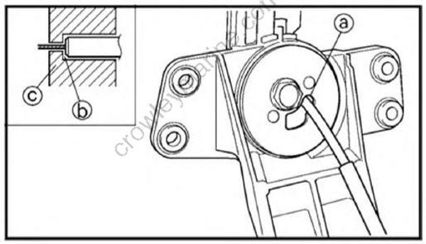
- Install:
• Throttle cable
The throttle cable should be routed through the cut (a) in the steering handle cover with the outer tube end (b) in contact with the step (c) in the steering handle.
EXPLODED DIAGRAM
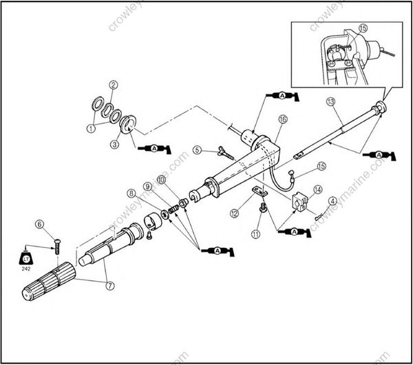
REMOVAL AND INSTALLATION CHART
| Step | Procedure/Part name | Q'ty | Service points |
|---|---|---|---|
| STEERING HANDLE DISASSEMBLY | Follow the left "Step" for disassembly. | ||
| Steering handle ass'y | |||
| (1) | Metal washer | 2 | |
| (2) | Wave washer | 1 | |
| (3) | Collar | 1 | |
| (4) | Cotter pin | 1 | |
| (5) | Friction adjusting screw | 1 | |
| (6) | Screw | 1 | |
| (7) | Steering grip | 1 | |
| (8) | Washer | 1 |
EXPLODED DIAGRAM
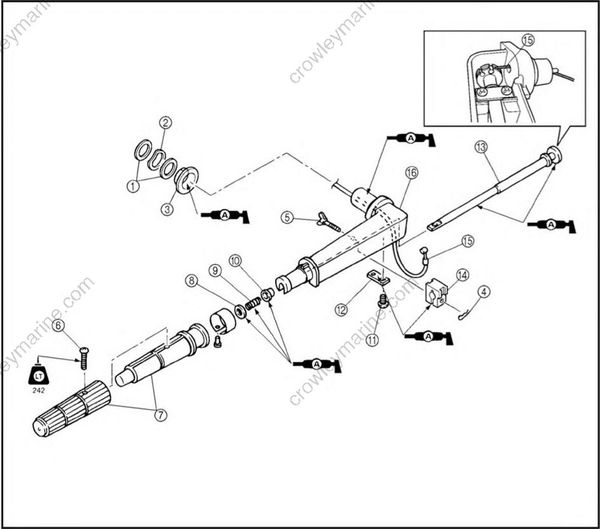
| Step | Procedure/Part name | Q'ty | Service points |
|---|---|---|---|
| (9) | Spring | 1 | |
| (10) | Bushing | 1 | |
| (11) | Bolt | 2 | |
| (12) | Plate | 1 | |
| (13) | Throttle shaft | 1 | |
| (14) | Friction piece | 1 | |
| (15) | Throttle cable | 1 | |
| (16) | Steering handle | 1 | |
| Reverse the disassembly steps for assembly. |
