

PTT motor
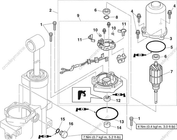
| No | Part name | Q’ty | Remarks |
|---|---|---|---|
| 1 | Bolt | 3 | M5 x 20 mm |
| 2 | PTT motor assembly | 1 | |
| 3 | Stator | 1 | |
| 4 | Screw | 3 | M5 x 15 mm |
| 5 | O-ring | 1 | Not reusable |
| 6 | Bearing | 2 | |
| 7 | Armature | 1 | |
| 8 | Wave washer | 1 | |
| 9 | Motor base assembly | 1 | |
| 10 | Spring | 2 | |
| 11 | Brush | 2 | |
| 12 | Oil seal | 1 | Not reusable |
| 13 | O-ring | 1 | Not reusable |
| 14 | Joint | 1 | |
| 15 | O-ring | 1 | |
| 16 | Reservoir cap | 1 | M12 x 10 mm |
Removing the PTT motor
WARNING
Before removing the reservoir, make sure that the trim and tilt ram is fully extended. Otherwise, fluid could be expelled forcefully from the PTT unit due to internal pressure.
Fully extend the trim and tilt ram.
Remove the reservoir cap “1”, and then drain the PTT fluid.

- Remove the PTT motor assembly “1”, O-ring “2”, and joint “3”.

Disassembling the PTT motor
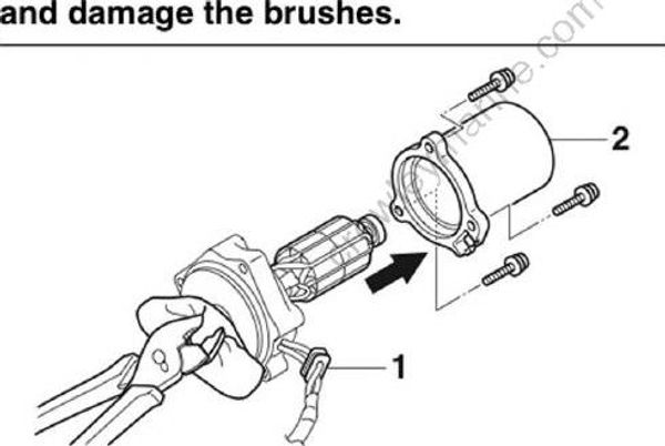
- Remove the rubber “1” from the stator “2”, and then remove the stator “2”.
NOTICE
Secure the end of the armature shaft using a pair of pliers, and then remove the armature along with the motor base assembly. Otherwise, the armature could separate from the motor base assembly due to the magnetic force of the stator “2”
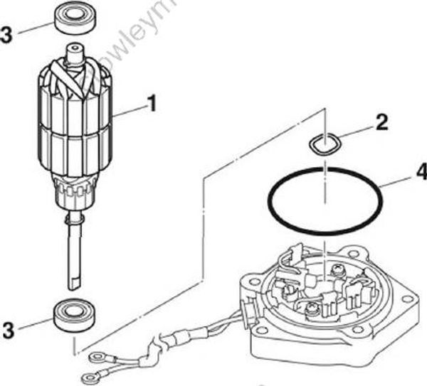
- Remove the armature “1”, wave washer “2”, bearings “3”, and O-ring “4”.
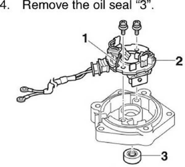
Disconnect the PTT motor lead “1”, and then remove the brush holder “2”.
Remove the oil seal “3”
- Disconnect the PTT motor lead “1”, and then remove the springs “2”, brushes “3”, and circuit breaker “4”.

Checking the armature (PTT motor)
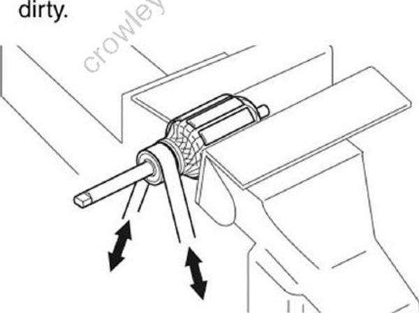
- Check the commutator. Clean using 600-grit sandpaper and compressed air if dirty.
- Measure the commutator diameter “a”. Replace the armature if below specification.

Motor commutator standard diameter “a”: 19.00 mm (0.7480 in)
Wear limit: 18.00 mm (0.7087 in)
- Measure the commutator undercut “a”.

Motor commutator standard undercut “a” (reference data): 1.50 mm (0.0591 in)
Wear limit: 1.00 mm (0.0394 in)
- Check the armature for continuity. Replace if out of specification.
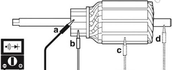
Digital multimeter: YU-34899-A
Armature continuity:
- Continuity: “a”-”b”
- No continuity: “a”-”c” “a”-”d”
Checking the brush
- Measure the length of each brush. Replace if below specification.
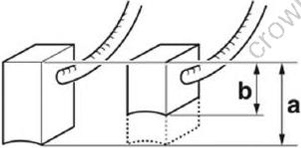
Brush standard length “a”: 11.00 mm (0.4331 in)
Wear limit “b”: 4.5 mm (0.1772 in)
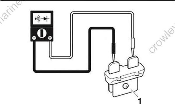
- Check the circuit breaker for continuity. Replace if there is no continuity.
NOTICE
Do not touch the bimetal “1”. Otherwise, the operation of the circuit breaker can be affected.
Assembling the PTT motor
NOTICE
Do not apply grease or oil to the commutator of the armature.
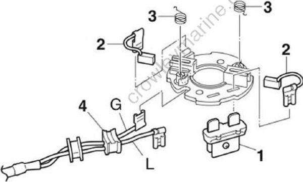
- Install the circuit breaker “1”, brushes “2”, and springs “3”, and then connect the PTT motor lead “4”.
Install a new oil seal “1”.
Install the brush holder “2”, and then connect the PTT motor lead “3”.

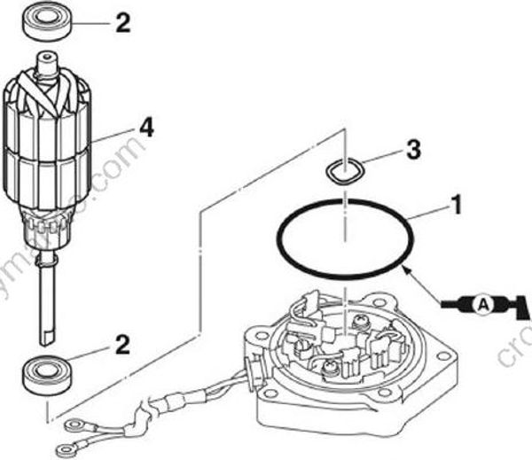
- Install a new O-ring “1”, and then install the bearings “2” and wave washer “3” to the armature “4”.
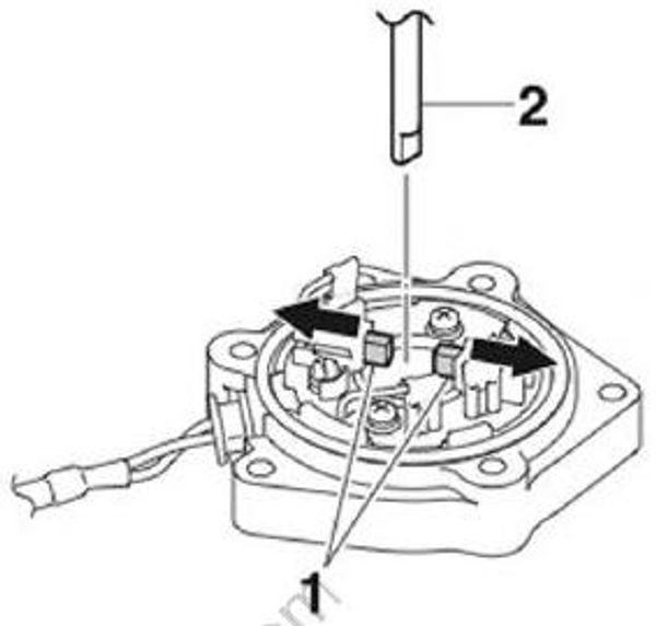
- Push the brushes “1” into the brush holder, and then install the armature “2”.
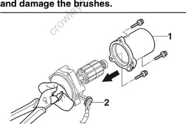
- Install the stator “1”, and then install the rubber “2” to the stator “1”. 9-57
NOTICE
Secure the end of the armature shaft using a pair of pliers, and then install the armature along with the motor base assembly. Otherwise, the armature could separate from the motor base assembly due to the magnetic force of the stator “1” and damage the brushes.
Installing the PTT motor
- Install the joint “1”, a new O-ring “2”, and the PTT motor assembly “3”, and then tighten the PTT motor assembly bolts “4” to the specified torque.
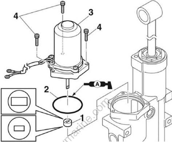
PTT motor assembly bolt “4”: 4 Nm (0.4 kgf-m, 3.0 ft lb)
- Install a new O-ring “1” and the reservoir cap “2”, and then tighten the reservoir cap “2” to the specified torque.
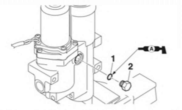
Reservoir cap “2”: 7 Nm (0.7 kgf-m, 5.2 ft-lb)
