

EXPLODED DIAGRAM
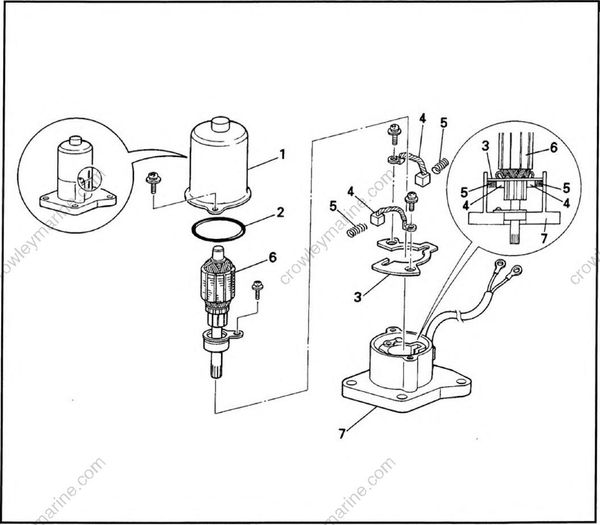
REMOVAL AND INSTALLATION CHART
| Step | Procedure/Part name | Q'ty | Service points |
|---|---|---|---|
| PTT MOTOR DISASSEMBLY | Follow the left "Step" for removal. | ||
| 1 | Stator | 1 | |
| 2 | O-ring | 1 | 49.5 x 2.0 mm |
| 3 | Brush holder | 1 | |
| 4 | Brush | 2 | |
| 5 | Brush spring | 2 | |
| 6 | Armature | 1 | |
| 7 | PTT motor base | 1 | |
| Reverse the disassembly steps for installation. |
SERVICE POINTS
Motor inspection
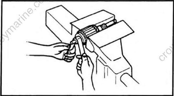
- Inspect:
- Commutator
Dirt -> Clean with #600 grit sandpaper.
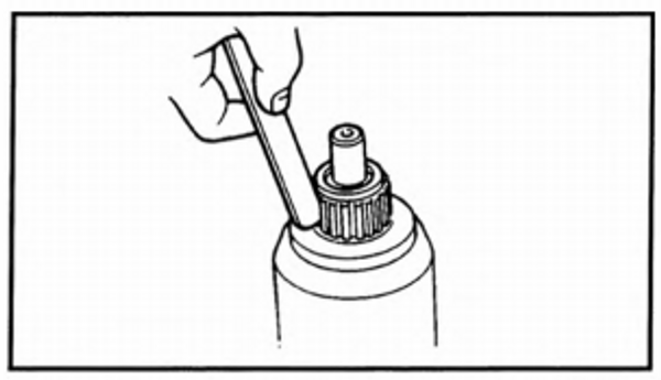
- Inspect:
- Segment undercut Obstruction -> Clean.
Remove all metal particles with com pressed air.
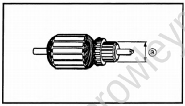
- Measure:
- Commutator diameter(a)
Out of specification -> Replace.
Commutator diameter limit: 15.5 mm (0.61 in)
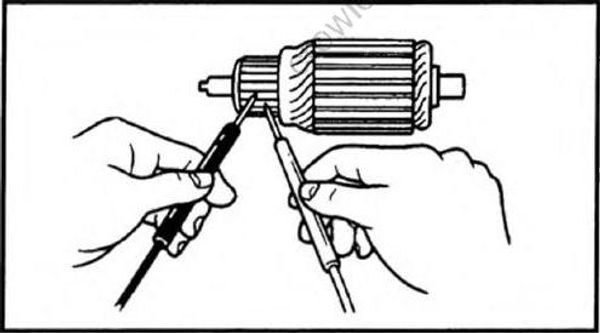
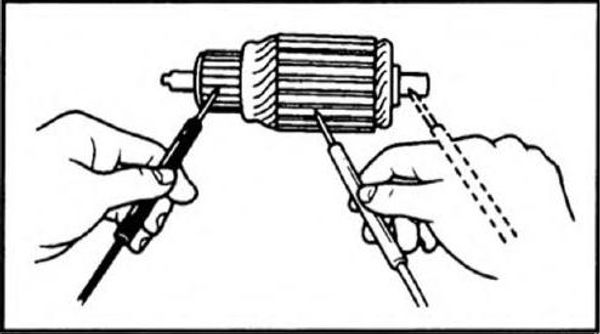
- Measure:
- Armature coil continuity
Out of specification -> Replace.
| Armature coil continuity | |
|---|---|
| Commutator segments | Continuity |
| Segment - laminations | No continuity |
| Segment - shaft | No continuity |
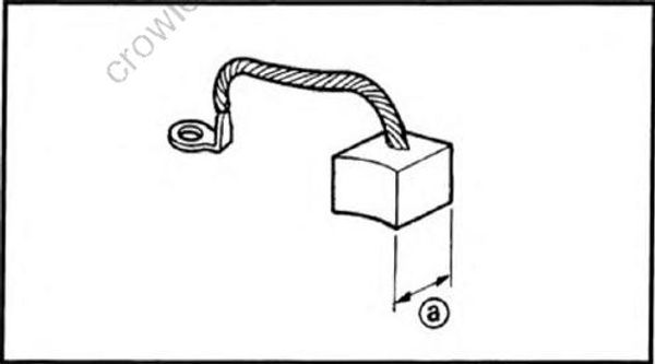
- Measure:
- Brush length (a)
Out of specification -» Replace.
Brush length limit: 3 mm (0.12 in)
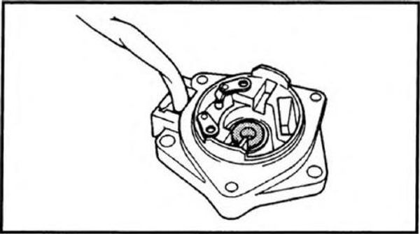
- Inspect:
- PTT motor base
Cracks/damage -> Replace.
- Inspect:
- Stator bushing
- PTT motor base bushing
Cracks/damage —> Replace.
- Inspect:
- PTT motor base oil seal
Damage/wear -> Replace.
PTT motor assembly
- Check:
- PTT motor operation
Incorrect operation -> Repair.
| PTT motor operation | |
|---|---|
| Blue (+), Green (-) | Motor turns clockwise |
| Green (+), Blue (-) | Motor turns counterclockwise |
