

Clamp brackets
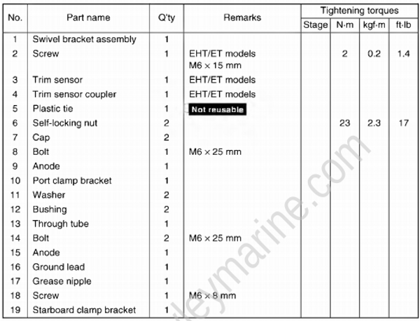
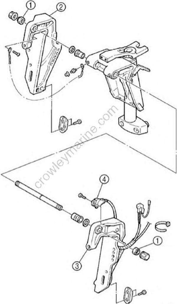
Removing the clamp brackets
Remove the power trim and tilt or hydro tilt. For removing procedures, see “Removing the power trim and tilt/hydro tilt” in this chapter.
Loosen the self-locking nuts (1), and then remove clamp brackets (2) and (3).
Remove the trim sensor (4).
Installing the clamp brackets
- Install the trim sensor (1) onto the port clamp brackets.
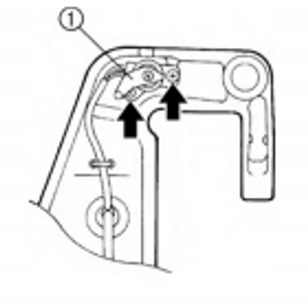
Adjust the trim sensor after installing the power trim and tilt.
- Assemble the clamp brackets and the swivel bracket by installing the self-locking nuts (2), then tightening them to the specified torque.
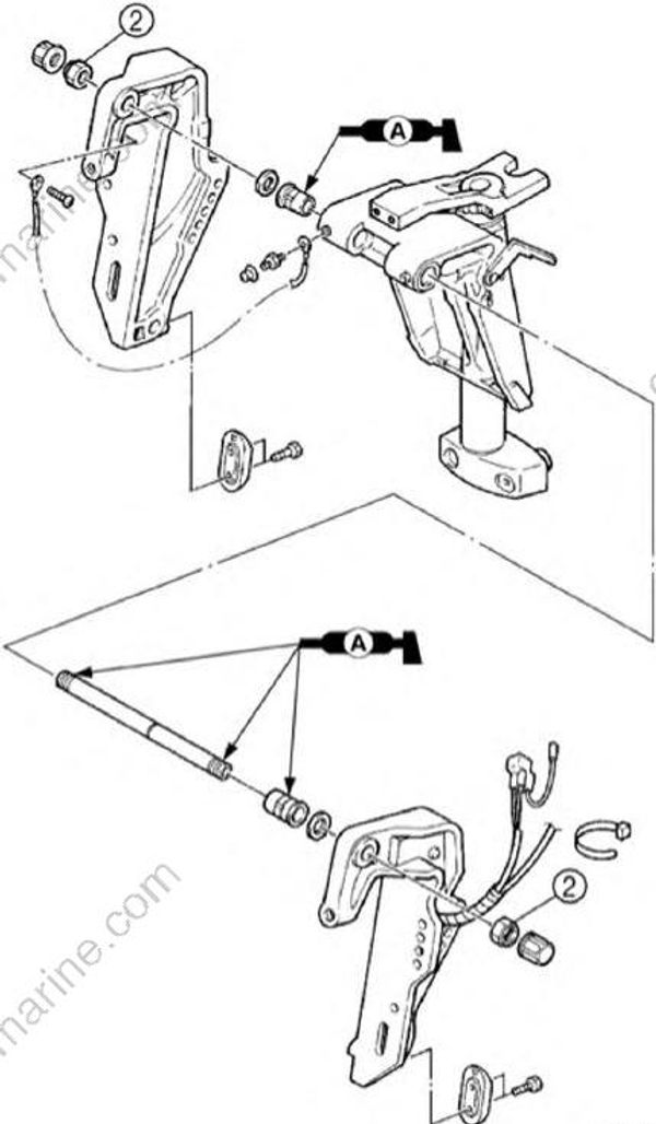
Self-locking nut 23 N•m (2.3 kgf•m, 17 ft•lb)
Install the power trim and tilt or hydro tilt. For installing procedures, see “Installing the power trim and tilt” in this chapter.
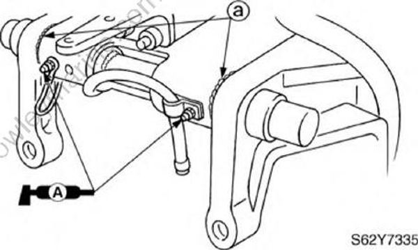
Inject grease into both grease nipples until grease comes out from the bushings (a).
Adjusting the trim sensor
- Fully tilt the outboard up, and then sup port it with the tilt stop lever (1).
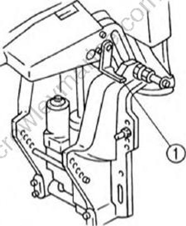
After tilting up the outboard, be sure to support it with the tilt stop lever. Otherwise, the outboard could suddenly lower if the power trim and tilt unit should lose fluid pressure.
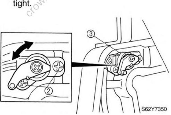
Loosen the cam screws (2).
Adjust the position of the trim sensor (3), and then tighten the screws (2) finger tight.
Fully tilt the outboard down.
Measure the trim sensor resistance. Repeat steps 1-5 if out of specification.
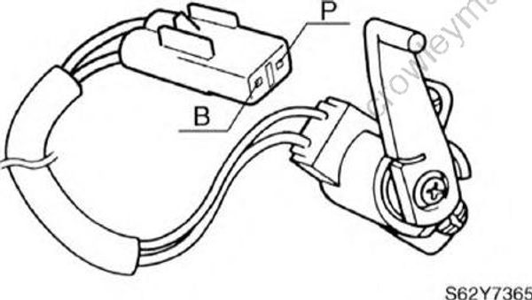
Trim sensor setting resistance: Pink (P) - Black (B) 9-11 Ω at 20 °C (68 °F)
- Fully tilt the outboard up, and then sup port it with the tilt stop lever.
After tilting up the outboard, be sure to support it with the tilt stop lever. Otherwise, the outboard could suddenly lower if the power trim and tilt unit should lose fluid pressure.
- Tighten the cam screws (2) to the specified torque.
Trim sensor cam screw (2): 2 N•m (0.2 kgf•m, 1.4 ft•lb)
- Fully tilt the outboard down.
