

Preface
This AC Lighting Kit can be used on CE and newer 4 through 45 Evinrude® and Johnson® outboards without alternators that use a CD2U ignition system. With this lighting kit installed, the motor provides 12 volt A.C. (Alternating Current) electrical power for the boat lights while the motor is running.
The installation of this kit involves procedures that require special training for the installer, plus the installation may require special tools and/or Service Manuals and other literature.
Service Technicians at your Dealer have received special training and have the equipment, special tools, and reference literature for your product. We recommend that you have this kit installed by your Dealer.
To the Installer
Give these installation instructions to owner. These instructions contain operating information important to the customer.
To the Owner
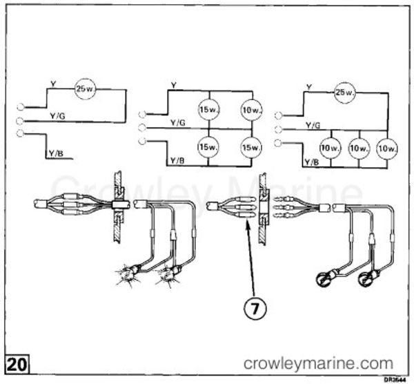
These installation instructions contain important operating information for your use. Keep them with your Owner's Manual. Refer to Figure 20 and the OPERATION instructions on Page 7 for boat wiring and light bulb selection.

[1]
Read instructions prior to starting work. Check Contents of kit:
| Ref. | Name of Part | Qty |
|---|---|---|
| 1 | Stator Assembly | 1 |
| 2 | Stator Screws | 2 |
| 3 | Bullet Terminal | 3 |
| 4 | Bullet Sleeve | 3 |
| 5 | Grommet and Cap | 1 |
| 6 | Tie Strap | 2 |
| 7 | Cap | 3 |
To avoid accidental starting of engine, twist and remove all spark plug leads
Remove manual starter housing (if equipped), flywheel and ignition plate assembly. Follow the procedures in the Service Manual for removal.
Install Stator Assembly
[2]
Remove two screws and clamp (A), and retain for reassembly.
[3]
Turn ignition plate over and remove screw and cover (B) and retain for reassembly.
[4]
Remove the ignition module mounting screw (C) and spacer (D). Retain screw and discard spacer.
[5]
Insert stator cable through the opening in the ignition plate.
[6]
Mount stator onto the ignition plate aligning three mounting holes with the ignition plate holes.
[6]
Apply Ultra Lock adhesive to threads of screws. Install stator mounting screws and washers (E). Install the third ignition module mounting screw and washer (C). Tighten screws finger tight.
[6] [7]
Reinstall top clamp and screws (A). Install bottom cover and screw (B) and tighten securely. Refer to the Service Manual for installation of ignition plate assembly.
Torque two stator mounting screws and one ignition module mounting screw to 30-40 in. lbs. (3,4-4,6 Nm.

[8]
4 thru 35 Models: Route stator cable through the J-clamp (F). Be sure the cable has slack at full throttle advance.
[9]
Route stator cable over the top of the engine to the port side and through the J-clamp (G).
[10]
40 - 45 Models: Route the stator cable along side the electrical box and down past the bottom of the box. Secure to box with tie strap allowing slack at full throttle.

[11] thru [16]
The above figures locate hole for cap and grommet. Center punch and drill a 13/16 in. dia. (20,6 mm) hole on the starboard side of the lower engine cover.
[17]
ES and newer 40-45 models: Cut a 3/8 in. (9,5 mm) vertical slit in center of rubber plug for wires.
[18]
Position grommet and cap assembly in lower engine cover, so that cap can be folded to fit in grommet.
OPERATION:
[19]
Boat Wiring: Place sleeve (4) on the yellow, yellow/gray, and yellow/blue boat wires. Strip 1/4 in. (6,4 mm) insulation off wires, and crimp bullet terminal (3) onto wires. Slide sleeve over terminal.
[20]
One side of each bulb must be connected to the yellow/gray (Y/G) COMMON wire. Always connect the boat Y/G wire to the motor Y/G wire. If either the yellow (Y) or yellow/blue (Y/B) wire is not used it must be protected from shorting to other wires. Motor wires must always be protected with Caps (7) when disconnected.
[20]
Bulb Selection: Use any of the bulb wattage combinations shown. Do not use more than 30 watts of power on either side or lights will be dim. Do not use less that 25 watts on either side (if connected) or the bulbs will burn out.
This wiring must not be connected to a battery or the electrical system will be damaged.