

Preface
This AC Lighting Kit can be used on 1983 and newer 4.5 thru 40 (except 40RP) rope start Evinrude® and Johnson® outboards without alternators, that use a CD II ignition system. With this lighting kit installed, the motor provides 12 volt A.C. (Alternating Current) electrical power for the boat lights while the motor is running.
The installation of this kit involves procedures that require special training the installer, plus the installation may require special tools and/or Service Manuals and other literature. We recommend that you have this kit installed by your Dealer.
To the Installer
Give these installation instructions to owner. These instructions contain operating information important to the customer.
To the Owner
These installation instructions contain important operating information for your use. Keep them with your Owner's Manual. Refer to Figure 9 and the OPERATION instructions on Page 6 for boat wiring and light bulb selection.
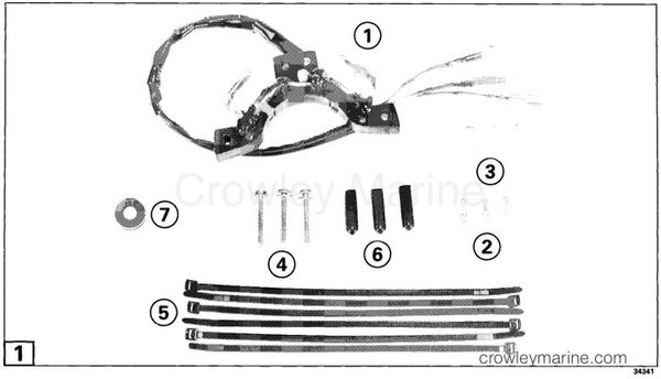
[1]
Read instructions prior to starting work. Check Contents of kit:
| Ref. | Name of Part | Qty |
|---|---|---|
| 1 | Stator Assembly | 1 |
| 2 | Bullet Terminal | 3 |
| 3 | Bullet Sleeve | 3 |
| 4 | Screw | 3 |
| 5 | Tie Strap | 6 |
| 6 | Cap | 3 |
| 7 | Grommet | 1 |
To avoid accidental starting of engine, twist and remove all spark plug leads.
Remove manual starter, flywheel, and ignition plate assembly.
Follow the procedures in the Service Manual.
[2]
Remove the wire clamp from the ignition plate.
[3]
Loosen the screw securing the wire cover (A). Route the bullet connectors through the opening until the slack is taken up between stator and ignition plate. Be sure wires are a single layer. Wires must not be twisted or overlapped.
Install the wire clamp and wire cover (A).
[4]
Apply Ultra Lock™ to the stator screws. Loosely install screws to retain stator to ignition plate.
Install the ignition plate on the powerhead. Follow the procedures in the Service Manual.
Check for sufficient slack on ignition component wires when ignition plate moves during throttle advancement.

[5]
Position Locating Ring, P/N 334994 over machined bosses on the ignition plate. Hold the ring in place and pull the stator out toward the ring. Torque screws to 30-40 in. lbs. (3,4-4,5 Nm).
[6]
Some models may require a hole in the lower cover for AC hook up. Locate an appropriate place that does not interfere with casting ribs, the powerhead, wires, etc. Drill a 1/2 in. (13 mm) diameter hole and insert the grommet supplied in kit.
Use the tie straps supplied to secure wires, sleeves, etc. to eliminate interference with any components. Different models require different tie strap usage.
[7]
Use caps supplied to cover bullet connectors when AC hook up is not being used.
OPERATION:
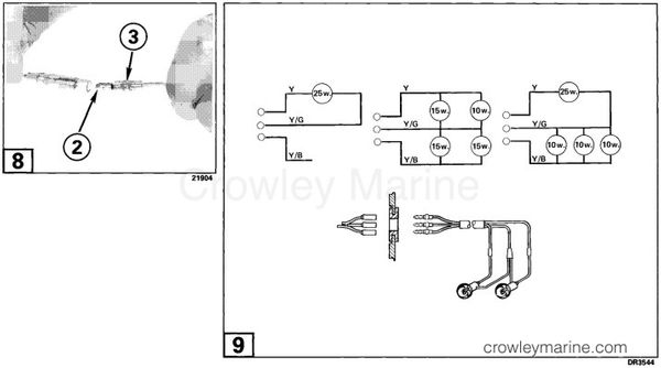
[8]
Boat Wiring: Place sleeve (3) on the yellow, yellow/gray, and yellow/blue boat wires. strip 1/4 in. (6,4 mm) insulation off wires, and crimp bullet terminal (2) onto wires. Slide sleeve over terminal.
[9]
One side of each bulb must be connected to the yellow/gray (Y/G) COMMON wire. Connect the boat Y/G wire to the motor Y/G wire. If either the yellow (Y) or yellow/blue (Y/B) wire is not used it must be protected from shorting to other wires. Motor wires must be protected with caps (6) when disconnected.
[10]
Bulb Selection: Use any of the bulb wattage combinations shown. Do not use more than 30 watts of power on either side or lights will be dim. Do not use less than 25 watts on either side (if connected) or the bulbs will burn out.
NOTE: This wiring must not be connected to a battery or the electrical system will be damaged.
0584861 - AC Lighting Kit
0334994 - Johnson/Evinrude, OMC Coil Locating Tool