

Preface
This 4 model water pump repair kit contains parts for both two- and three-screw water pumps. On assembly of the two-screw water pump model, discard one of the screws supplied to kit.
Actions to be Performed
Step 1. Preparation for Installation
Step 2. Assembly of Water Pump
Step 3. Installation of Water Pump
Step 1. Preparation for Installation
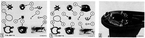
1. Read complete installation instructions prior to starting work.
[1]
2a. Check contents of kit P/N 394115 to become familiar with components.
P/N 394115
| Ref. | P/N | Description | Qty. |
|---|---|---|---|
| * | 394115 | Water Pump Kit | 1 |
| 1 | 300611 | . Dowel Pin | 1 |
| 2 | 303191 | . O-Ring | 1 |
| 3 | 321127 | . Screw - Water Pump | 3 |
| 4 | 321129 | . Grommet - Water Tube | 1 |
| 5 | 321283 | . O-Ring | 1 |
| 6 | 324641 | . Imp, Hsg, Cup | 1 |
| 7 | 329092 | . Plate - Imp, Hsg. | 1 |
| 8 | 330447 | . Gasket | 1 |
| 9 | 389576 | . Impeller Assy | 1 |
| 10 | . Moly Lube | 1 |
[1]
Check contents of kit P/N 394116 to become familiar with components.
P/N 394116
| Ref. | P/N | Description | Qty. |
|---|---|---|---|
| * | 394116 | Water Pump Kit | 1 |
| 1 | 300611 | . Dowel Pin | 1 |
| 2 | 303191 | . O-Ring | 1 |
| 3 | 321127 | . Screw - Water Pump | 3 |
| 4 | 321129 | . Grommet - Water Tube | 1 |
| 5 | 324641 | . Imp, Hsg, Cup | 1 |
| 6 | 329091 | . Impeller Hsg. | 1 |
| 7 | 329092 | . Plate - Imp. Hsg. | 1 |
| 8 | 330342 | . Seal | 1 |
| 9 | 330447 | . Gasket | 1 |
| 10 | 389576 | . Impeller Assy | 1 |
| 11 | . Moly Lube | 1 |
- Not Shown
3. Obtain following lubricants and sealants not supplied in kit: Gasket Sealing Compound P/N 317201, Triple-guard Grease P/N 173653 and a light oil.
4. Refer to Service Manual for removal of the gearcase from the exhaust housing.
5. Remove worm or damaged water pump assembly from gearcase.
[2]
6. Remove and clean water intake screen.

[3] 7. Clean all sealant from gearcase impeller plate surface.
Step 2. Assembly of Water Pump
[4]
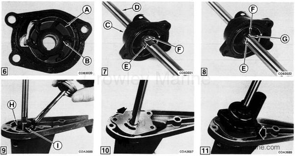
1. Apply small amount of Triple-Guard Grease to groove (A) around bottom of impeller housing and install large O-ring (B).
[5]
2. Install impeller cup (C) into impeller housing (D).
[6]
3. Apply a light coat of Triple-Guard Grease to impeller cup (A). Install impeller (B) into cup with a counterclockwise rotation.
[7]
4. Slide water pump assembly (C) onto driveshaft (D). Align flat (E) of driveshaft with drive pin slot (F) of impeller.
[8]
5. Place impeller drive pin (G) on flat (E) of driveshaft and slide water pump assembly down, engaging drive pin slot (F) of impeller.
Step 3. Installation of Water Pump
[9]
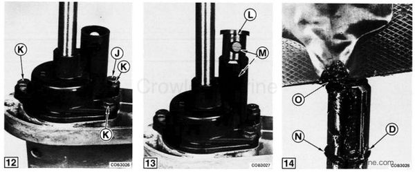
1. Install water intake screen (H) onto gearcase. Apply Gasket Sealing Compound P/N 0317201 (I) to gasket surface of gearcase. Align and install gasket onto gearcase.
[10]
2. Align and install impeller plate onto gasket.
[11]
3. Align and install driveshaft and water pump assembly to gearcase.
[12]
4. On assembly of two-screw water pump model, discard one screw (J). Tighten two screws to a torque of 7-9 Nm (60-80 in. lbs.).
[12]
5. On assembly of three-screw water pump models, install three screws (K) provided in kit. Tighten screws to a torque of 7-9 Nm (60-80 in. lbs.).
[13]
6. Install water tube grommet (L) into impeller housing, locating tabs (M) of grommet into holes of impeller housing.
[14]
7. Install driveshaft O-ring (N) into groove of driveshaft (D). Apply Moly-Lube (O), supplied in kit, to driveshaft splines.
- Reinstall gearcase onto exhaust housing, being sure to engage water tube into water tube grommet.