

Trim-up and tilt-up function
Pushing the UP button on the PTT switch causes the PTT motor “1” to activate the gear pump “2”, generating the PTT fluid pressure. The PTT fluid pressure moves the up-main valve “3” and down main valve “4”.
The PTT fluid passes through the up passage and flows into the lower chamber of the trim cylinder “5”. The PTT fluid pressure pushes up the trim cylinder “5”, and the PTT fluid in the upper chamber of the trim cylinder passes through the down passage, returning to the gear pump. The valve “6” opens when the trim cylinder is pushed to its upper extreme.
The PTT fluid pressure pushes up the tilt piston “7”, and the PTT fluid in the upper chamber of the tilt cylinder passes through the down passage, returning to the gear pump. When the tilt-up operation is complete, the PTT fluid pressure increases causing the up-relief valve “8” to open, and the PTT fluid returns to the reservoir “a”.
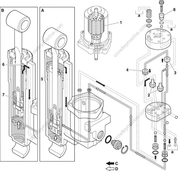
A. Trim range
B. Tilt range
C. Return circuit
D. Send circuit
Trim-down and tilt-down function
Pushing the DN button on the PTT switch causes the PTT motor “1” to activate the gear pump “2”, generating the PTT fluid pressure. The PTT fluid pressure moves the down-main valve “3” and up main valve “4”.
The PTT fluid passes through the down passage and flows into the tilt cylinder, pushing down the tilt piston “5”. The PTT fluid in the lower chamber of the tilt cylinder passes through the up passage, returning to the gear pump.
The trim cylinder “6” is pushed down when the tilt cylinder is filled with the PTT fluid.
The PTT fluid in the lower chamber of the trim cylinder passes through the up passage and returns to the gear pump.
When the tilt-down operation is complete, the PTT fluid pressure increases causing the down-relief valve “7” to open. The PTT fluid returns to the reservoir “a”.
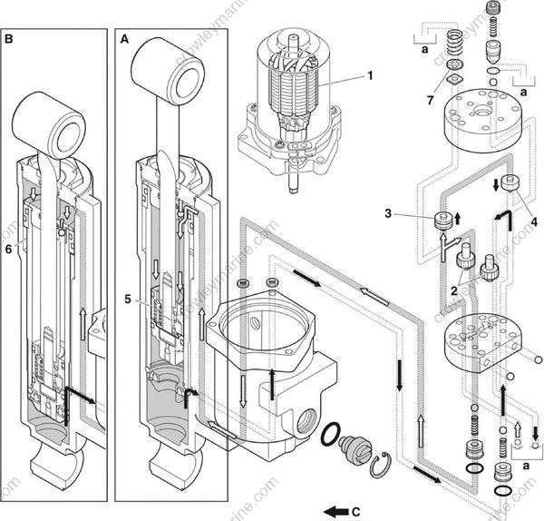
A. Tilt range
B. Trim range
C. Return circuit
D. Send circuit
Stationary condition
When the PTT switch is not pushed, the gear pump will not pump the PTT fluid, the up-main valve and down-main valve will remain closed, and the PTT fluid in the system will remain at a constant pressure. As a result, the trim and tilt ram stays in its current position.
Shock-absorbing function
If the lower case strikes an obstacle while the boat is moving, a force causing the trim and tilt ram “1” to extend will be applied.
Because this force will cause the PTT fluid pressure in the tilt cylinder upper chamber “a” to increase, the tilt piston absorber valve “2” will open.
The PTT fluid enters the space between the tilt piston “3” and the free piston “4” extending the trim and tilt ram “1”.
The damping effect of the absorber valve stops the tilt piston before it reaches the top of the tilt cylinder.
After the collision with an obstacle, a force is generated as the outboard motor returns to its original position due to the weight of the outboard motor and the thrust of the propeller. The PTT fluid enters the tilt cylinder upper chamber “a” through the shock return valve “5” in the tilt piston “3”. The trim and tilt ram “1” stops when it contacts the free piston “4”.
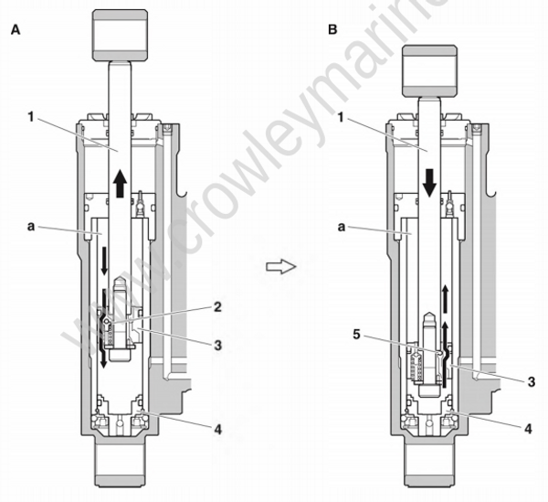
A. Fluid flow when the outboard motor strikes an obstacle.
B. Fluid flow when the outboard motor returns to the original position.
