

LOCATION OF PARTS
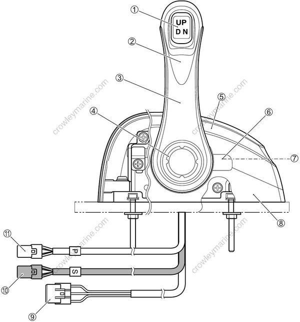
(1) PTT switch
(2) Grip
(3) Remote control lever
(4) Decal (SUZUKI)
(5) Upper cover
(6) Grommet
(7) Friction adjust screw
(8) Lower cover
(9) PTT connector
(10) Wire harness connector (Dual type only)
(11) Wire harness connector
DIMENSIONS
(Single Type)
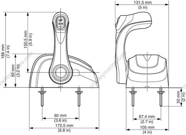
(Dual Type)
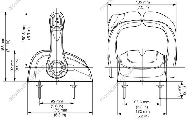
REMOTE CONTROL LEVER OPERATING RANGE
- Forward
To shift into forward, push the remote control lever forward and downward thru approx. 17° on (F) side (A). When motor is in gear, push the control lever further downward will open the throttle.
- Reverse
To shift into reverse, pull the remote control lever backward and downward thru approx. 17° on (R) side (B). When motor is in gear, push the control lever further downward will open the throttle.
REMOTE CONTROL LEVER FRICTION ADJUSTMENT
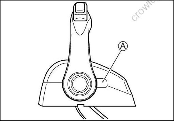
ADJUSTMENT
Adjust the lever friction in the following procedure.
(1) Remove the grommet (A).
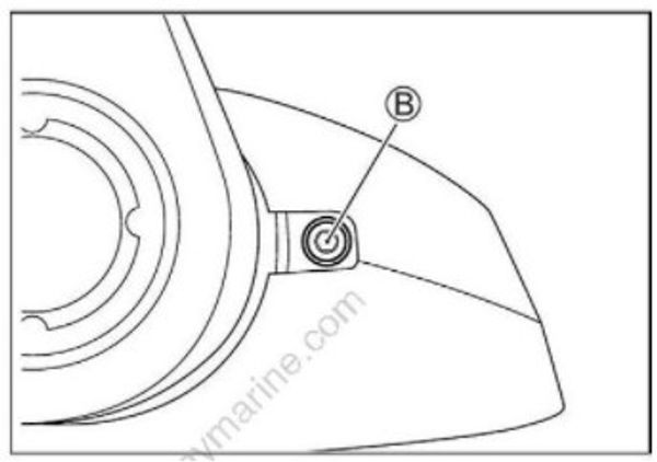
(2) Turn the adjusting screw (B) with a hexagon wrench.
Turning clockwise → increase tension
Turning counterclockwise → decrease tension
Be careful when tightening the adjusting screw so that the tightening torque does not exceed 2.5 N·m.
(3) Install a grommet (A).
CHANGE OF DETENT SPRING
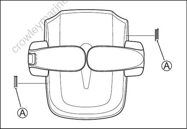
Replace the detent spring in the following procedure.
Though the control shown in the right figure is a dual remote control, the replacement procedure for the single remote control is the same.
(1) Remove the grommet (A) from the remote control box.
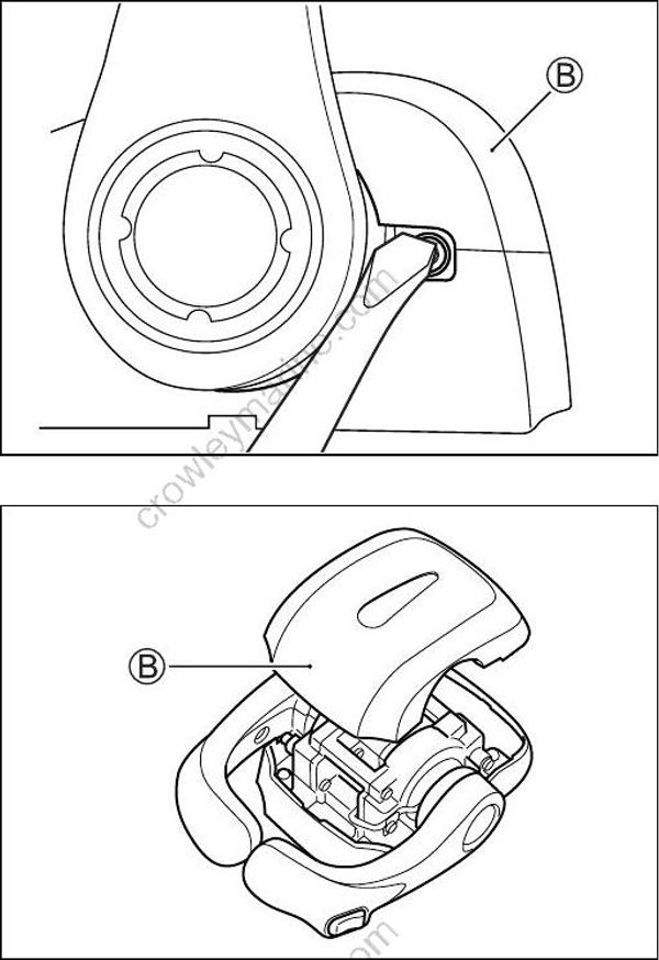
(2) Insert the flat screw driver into the grommet (A) installing hole, then pry the upper cover (B) off from the remote control box.
(3) Move the remote control lever in the forward direction to the throttle full open position.
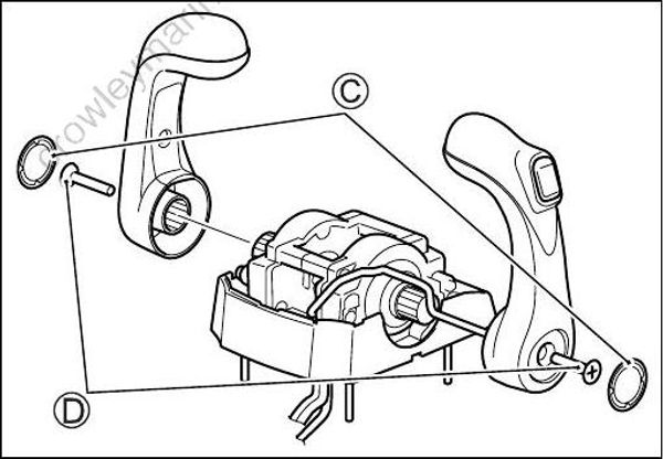
(4) Take off the decal (C) from the remote control lever. Remove the screw (D) and remove the control lever.
Decal cannot be reused.
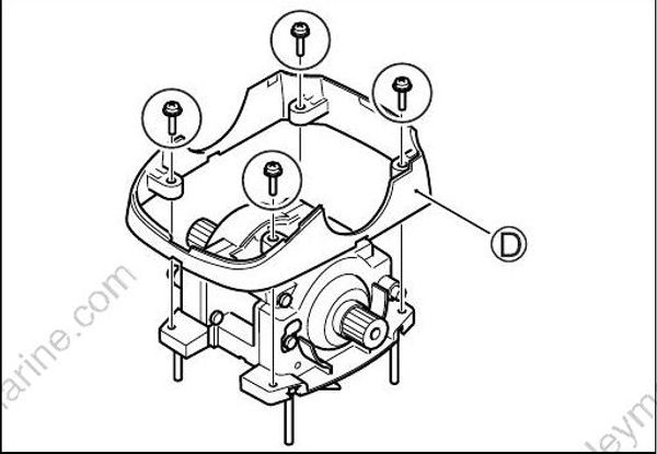
(5) Remove the four (4) screws securing lower cover (D), then remove the lower cover.
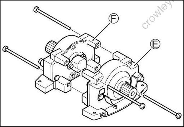
(6) Remove the four (4) screws from the remote control box and separate the port side housing (E) and starboard housing (F).
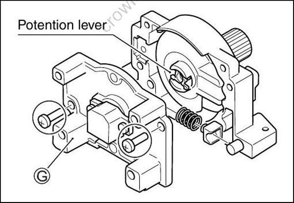
(7) Remove the two (2) screws and back panel assembly (G).
Keep the potention lever attached to the drive shaft.
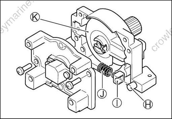
(8) Remove the roller (H), roller guide (I), and detent spring (J) from the drive shaft (K).
(9) Replace the detent spring (J).
When assembling, coat the sliding areas of the potention lever, roller, roller guide and detent spring with water-resistant grease.
99000-25160: Water resistant grease
ASSEMBLING
Assemble the components in the reverse order to disassembly. Be careful for the following points when assembling the components:
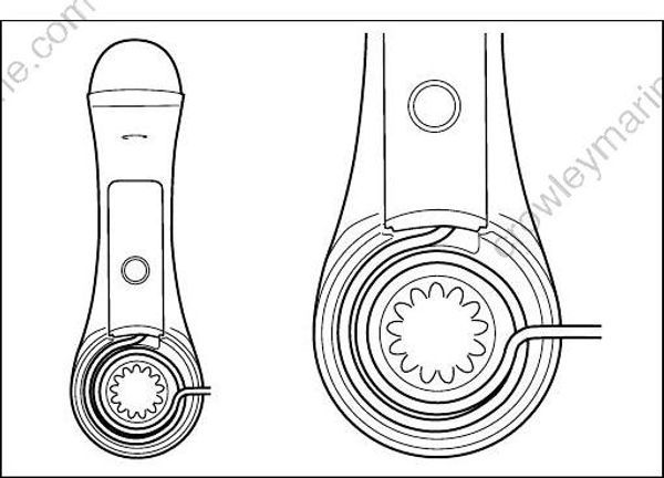
- Wind the switch lead wire of the lever with a power trim & tilt switch around the boss at the center of the control lever one turn and a half counterclockwise, from the outside to inside.
REMOTE CONTROL POSITION
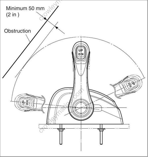
Set the Remote Control Box in a position in which it does not obstruct the operations of the control lever and switches. Make sure there is no obstruction on the path of the remote control wire harness.
Allow a space so that the bottom of the Remote Control Box does not contact any other parts.
Provide a space so that the remote control wire harness can be routed without vending sharply.
• Do not cut or extend the wiring harness and lead wires of the remote control box. Water may enter from the joint of the wiring harness or lead wire, causing a continuity error at the connections and shifting and throttle control errors.
• Put a water-proof cap to seal the connectors not in use.
CONTAINED PARTS
| Item | Part name | Part number | Q’ty |
|---|---|---|---|
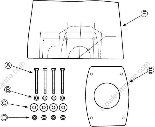
| (A) | Bolt (M5-50 mm) | 67226-98J00 | 4 |
| (B) | Washer (10 mm OD) | 67288-98J40 | 4 |
| (C) | Washer (16 mm OD) | 09160-05024 | 4 |
| (D) | Nut (M5) | 67287-92E00 | 4 |
| (E) | Seal (Single type) | 67273-98J00 | 1 |
| (E) | Seal (Dual type) | 67273-98J20 | 1 |
| (F) | Template | ——— | 1 |
INSTALLATION
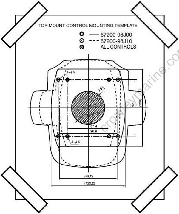
(1) Select the proper position of the remote control box, and stick the template on the selected position.
(2) Then drill one of φ54 mm hole and four of φ6 mm holes through the template.
After drilling the holes, make sure opening is free of sharp edges.
(3) Route wiring for the remote control into opening and connect with the remote control box.
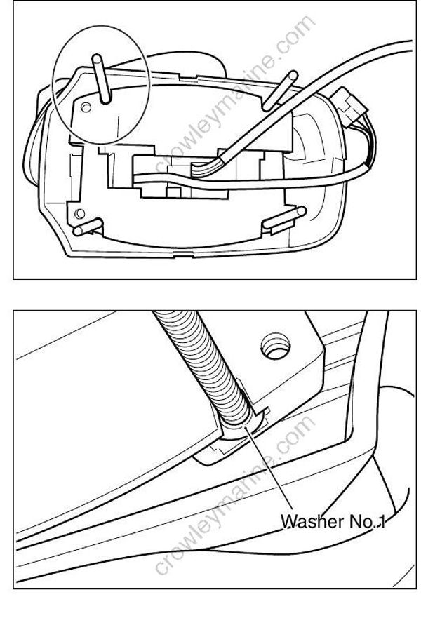
(4) Insert 4 bolts to the 4 holes on the plate of the bottom of remote control box.
Don’t forget installing the washer No.1 with the bolt.
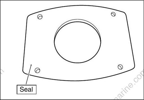
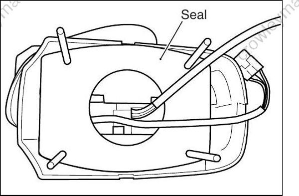
(5) Attach the seal to the bottom of remote control box as putting through the bolts.

(6) Install the remote control box using the nut and the washer No.2 to the console.
