

Ignition System Static Test
Perform the static ignition test using Evinrude Diagnostics software and an inductive timing light.
IMPORTANT: DO NOT use a spark checker tool. Radio Frequency Interference (RFI) generated by the arcing current can cause erratic EMM operation.
The outboard must NOT be running and the emergency stop switch lanyard must be installed.
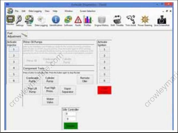
Testing, Static Test Screen
Connect timing light pickup to the secondary circuit (spark plug lead) of the cylinder being tested. Activate test and observe timing light strobe for consistent flash.
IMPORTANT: You may need to remove shielding from wire if pickup does not read signal.
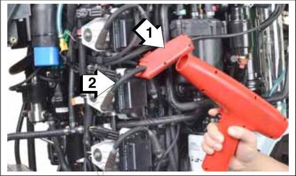
- Timing light pick-up
- Spark plug lead
Results:
No spark on one or more cylinders:
Inspect or replace spark plugs
Refer to Ignition Circuit Tests on p. 123
Refer to Ignition Coil Tests on p. 123.
Steady spark on all cylinders:
- Refer to Running Ignition Tests on p. 122 and Dynamic Tests on p. 108.
Fuel System Static Tests
Fuel Pump Static Test
Use the Evinrude Diagnostics software Fuel Pump test to activate the electric fuel pump. If the pump runs, the EMM and fuel pump circuit are not at fault
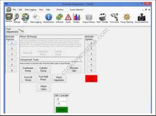
Static Tests Screen
If the pump does not run:
The EMM controls power to the fuel pump (purple/black wire). Check voltage at pin 1 of fuel pump connector. Voltage should be 12 V when KEY is first ON, when fuel pump test activated, or when outboard is cranking or running.
Use an ohmmeter to check continuity between pin 2 of fuel pump connector and ground.
Refer to Fuel Circulation Pump Resistance Test on p. 166. If the pump runs:
Refer to Fuel System Pressure Tests on p. 160.
Refer to Running Fuel System Tests on p. 160.
Fuel Injector Static Test
Use the Evinrude Diagnostics software Fuel Injector Static Test to activate each fuel injector. Listen for an audible click from each injector when it is actuated. If the injector activates, the EMM and injector circuits are not at fault.
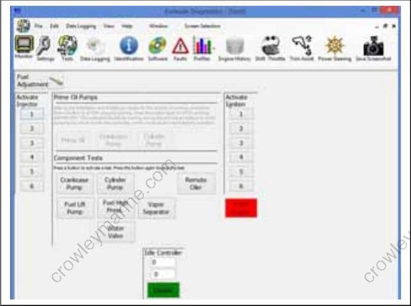
Static Tests Screen
IMPORTANT: This test is operating the injectors with 30 V on the system voltage (55 V) circuit. The start assist circuit (SAC) of the EMM converts battery voltage (12 V) to 30 V of system voltage. Battery must be fully charged and connections must be clean and tight. Injector activation should be carefully confirmed.
Results:
No injectors actuate:
Use the Monitor screen of the diagnostics software to make sure voltage is present on the system voltage circuit.
Refer to Running Fuel System Tests on p. 160.
Some injectors actuate; some do not:
For non-working injectors, test the resistance of individual injector circuits between the injector connector and injector control wire at the EMM.
See Fuel Injector Resistance Test on p. 167.
All injectors actuate:
- Refer to Running Fuel System Tests on p. 160.
Oil System Static Tests
Crankcase Oil Pump Static Test
IMPORTANT: Static tests operate the oil pumps with 30 V on the system voltage (55 V) circuit. The start assist circuit (SAC) of the EMM converts battery voltage (12 V) to 30 V of system voltage. The battery MUST be fully charged and connections must be clean and tight.
Oil pump activation should be carefully confirmed. Listen for an audible click from the oil pump when it is activated.
Crankcase Oil Pump Static Test
The EMM controls the pump by providing ground through pin 20 (blue wire) of the J1-B connector and pin B (blue wire) of the oil pump connector.
Use the Crankcase Pump test of Evinrude Diagnostic software Tests screen to activate the oil pump. This test activates the EMM control function for the oil pump.
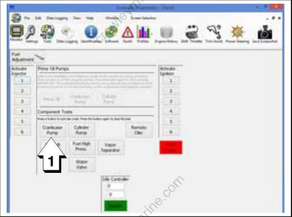
Tests Screen
- Crankcase Pump button
Use an inductive timing light to monitor current flow through the ground circuit (blue wire) at the oil pump connector (pin B).
Results:
If the light flashes, the EMM and oil pump circuits are not at fault.
If the light does not flash, refer to Oil Pump Electrical Tests on p. 198.
Cylinder Oil Pump Static Test
The EMM controls the pump by providing ground through pin 10 (blue/orange wire) of the J3 connector and pin B (blue/orange wire) of the oil pump connector.
Use the Cylinder Pump test of Evinrude Diagnostic software Tests screen to activate the oil pump. This test activates the EMM control function for the oil pump.
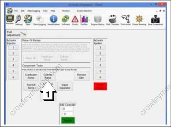
Tests Screen
- Cylinder Pump button
Use an inductive timing light to monitor current flow through the ground circuit (blue wire) at the oil pump connector (pin B).
Results:
- If the light flashes, the EMM and oil pump circuits are not at fault.
If the light does not flash, refer to Oil Pump Electrical Tests on p. 198.
Dynamic Power Steering (DPS)
Use the Power Steering screen of Evinrude Diagnostics software to observe DPS system reactions while turning the steering wheel.
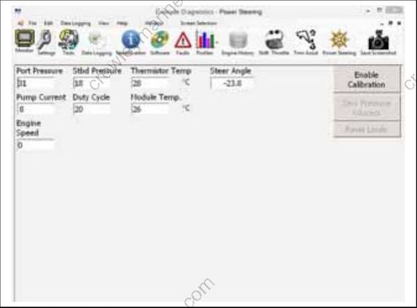
Power Steering Screen
