

Visual Inspections
Visual Inspections
Inspect wiring and electrical connections. Disassemble and clean all corroded connections. Replace damaged wiring, connectors, or terminals. Repair any shorted electrical circuits.
Refer to Electrical Harness Connections on p. 112.
Refer to WIRING DIAGRAM at the back of this manual.
Refer to Connector Servicing on p. 139.
Make sure all ground connections are clean and
tight. Refer to Ground Circuits on p. 115.
Inspect spark plugs for wear, oil fowling, or damage. A rich or lean running condition or evidence of internal engine damage could be identified by the appearance of the spark plugs.
Check the fuses and the emergency stop switch lanyard.
Diagnostic Software Inspections
Before running the outboard, use Evinrude Diagnostics software v 6.1 or higher to review information saved in the EMM.
Correct any problems and clear any fault codes before further troubleshooting. Refer to Faults and Fault Codes on p. 91.
Faults
Check the Faults Screen. Press the Active Faults button to view existing faults.
The Active Faults screen displays fault codes that currently exist. An active fault becomes an occurred fault only if the outboard is running.
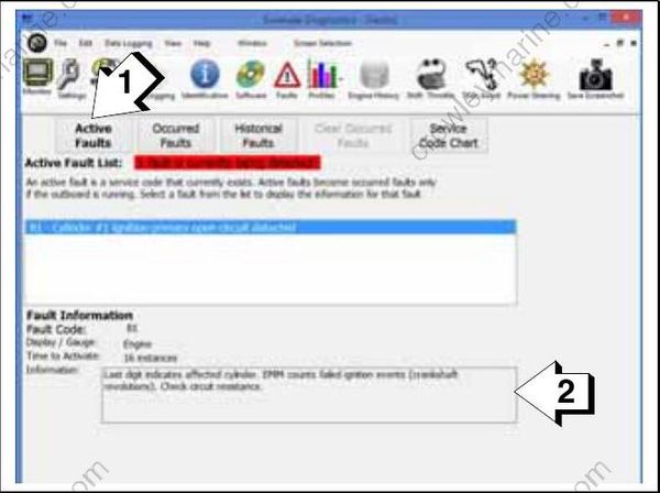
Active Faults Screen
- Active Faults button
- Information
Press the Occurred Faults button to view detailed information about the operating conditions of the engine at the time the fault code was set.
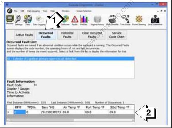
Occurred Faults Screen
- Occurred Faults button
- Detailed information
Profiles
Review information about how the outboard has been operated using the Profiles screens.
- Check the RPM Profile for long periods of low speed operation or periods of over-revving rpm
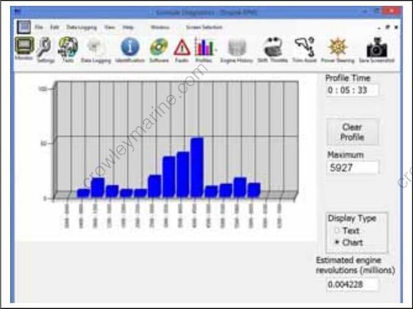
RPM Profile
- Check the Engine Temperature Profile for evidence of cold running or overheating.
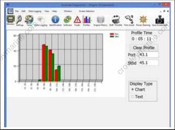
Engine Temperature Profile
History and Reports
View engine history and save reports from the History screen. Reports save a snap-shot of current engine and sensor conditions.
From the History screen:
Press the Create EDF button to create an engine data file. Engine data files are required when replacing an EMM.
Press the Running History button to view the Last Two Minutes of engine run history.
Press the Create Report button to create a new report (must be connected to/communicating with the engine EMM).
Press Open Exports Folder to view saved reports.
Press Show Selected Report to view a report selected from the Engine History Records List.
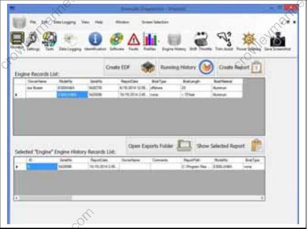
History Screen
- The Last Two Minutes report is generated and saved as part of the Engine Report. Engine runtime values during the last two minutes of operation above 1500 rpm is collected once per second. The newest record is first on the list. As each new record is added, the oldest record is removed.
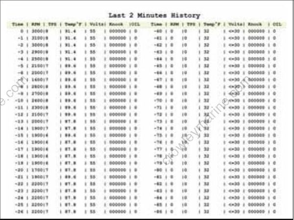
Last Two Minutes
Operational Inspections
Run the outboard to confirm actual symptoms before performing any unnecessary procedures. Inspection should include the following:
- Make sure the outboard can be cranked easily, with no mechanical binding.
Data Logging
Data Logging
Run the outboard in the water at all speeds. Be sure to run at any report problem engine speeds to confirm actual symptoms. Inspection should include the following:
- Use the diagnostics software Logging function to record engine data as a problem is occurring.
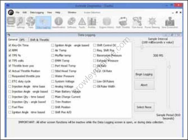
Logging Screen
Troubleshooting
Outboard will not crank, starter does not operate:
Check condition of battery and cables (main battery switch and cables). Make sure battery cables are not reversed.
Confirm that switched B+ is present at “A” terminal (purple wire) of starter solenoid with key switch in the ON position.
Refer to Electric Starter Tests on p. 131. Repair starter or start circuit as needed.
Outboard cranks, will not start:
Check emergency stop switch and lanyard
Use the Evinrude Diagnostics software Faults screens to check for current fault codes. If there are multiple occurred sensor codes, inspect all 5 V sensor circuits for broken or grounded wiring.
Perform a Static Ignition test using Evinrude Diagnostics software and an inductive timing light. Refer to Ignition System Static Test on p. 105.
If ignition test indicates steady spark, refer to Fuel System Static Tests on p. 105.
Outboard runs, low on power, misfires:
- Use the Evinrude Diagnostics software Monitor screen to check system (55 V) and TPS voltages. System voltage should be steady, and TPS voltage should be between 0.2 and 4.85 V.
IMPORTANT: Use a digital multimeter to check voltage on external circuits only when necessary. All EMM output currents are DC current.
Use the diagnostics software Dynamic Tests to isolate a faulty cylinder. See Dynamic Tests on p. 108.
Use an inductive timing light to check ignition and fuel injector circuits. Refer to Running Ignition Tests on p. 122 and Running Fuel System Tests on p. 160.
Use the diagnostics software Fuel Control Adjustment test to help identify a cylinder that may be too rich or too lean. Refer to Fuel Control Adjustment on p. 108.
Use an inductive amp meter to monitor injector circuit current. Compare readings of all circuits to identify possible failure.
Check fuel quality and that fuel is present at injectors.
AFTER all the above inspections, if the cause of a running quality problem still cannot be identified, perform a compression test to check for internal powerhead damage.
IMPORTANT: Remove a cylinder head or disassemble the engine only as a last resort.Voltage Regulator/Rectifier Continuity
Test
