

Routine Service
Install the anode and screw on the propeller shaft. Tighten the screw to 177 to 204 in. lbs. (20 to 23 N•m).
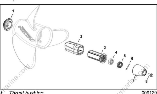
- Thrust bushing
- Torsion bushing
- Bushing and sleeve
- Propeller nut
- Keeper
- Cotter pin
- Anode
- Screw
IMPORTANT: After installation, make sure out board is in NEUTRAL and carefully spin propeller. Propeller must turn freely and should not spin off center. If propeller appears to wobble, check for possible bent propeller shaft.
Adjustments
An in the water test is required to make sure the outboard(s) and boat are rigged correctly, propeller selection is correct, and that all accessories function properly.
Pay special attention to the following, especially if the boat is re-powered with new outboard(s):
- Engine mounting height
- Jack plate adjustment
- Correct propeller selection and WOT RPM
- Fuel system vacuum
- Engine water pressure/optional water screens Make all needed adjustments or repairs and retest before delivery.
When ready for delivery, give all instruction sheets, operating instructions and user guides provided with accessories to the owner. Advise the owner of any special operation or maintenance information contained in the instructions.
IMPORTANT: Complete the Predelivery Check list and obtain owner’s signature at the time of delivery. The Predelivery Checklist must be kept on file for seven years.
Engine Mounting Height and Jack Plate Adjustment
Goals include:
- Engine RPM within the full throttle operating range
- Best acceleration and top speed
- No excessive ventilation while boat is coming onto plane.
Start with the engine lower on the transom. Make a test run, taking note of engine RPM, water pres sure, trim level and boat speed.
Raise the engine or jack plate and repeat the process until the best acceleration and boat speed are achieved.
Fuel System Vacuum
Test fuel system vacuum. Refer to Fuel Lift Pump Vacuum Test on p. 163. The maximum inlet fuel vacuum should not exceed 4 in. Hg. (13.5 kPa) at the inlet to the fuel lift pump under any operating conditions (IDLE to WOT).
A higher vacuum indicates an excessive restriction in the fuel supply. Repair as needed.
Engine Water Pressure
Check engine water pressure. Confirm adequate water pressure at all engine speeds and in turns. If water pressure falls below acceptable levels, adjust outboard alignment (multiple engine installations.
Trim & Tilt
The trim and tilt functions of Evinrude E-TEC G2 outboards are controlled by the engine EMM.
IMPORTANT: Activating any trim button while the key switch is in the OFF position will briefly turn on the system. This will cause the electric fuel pump to run and the remote control and any displays or gauges to turn on. There will be a short de lay before the trim system operates. This is normal. The system will turn off after a few seconds of non use.
Tilt Limit Setting
If the outboard does not clear all boat parts when tilted fully or turned side to side, safety related parts could be damaged in the course of such outboard movement. Injuries could result from loss of boat control.
Adjusting the tilt limit will NOT prevent the outboard from tilting fully and contacting the motor well if the gearcase hits an object at high speed. Such contact could damage the outboard and boat and injure boat occupants.
The tilt limit setting will not prevent the out- board from overriding the adjustment if the outboard is tilted manually.
Check the tilt limit on all new outboard installations.
Check the clearance between outboard(s) and the boat’s motor well and transom area. Tilt out board(s) to highest point of clearance and turn the steering system lock to lock.
If the outboard contacts the boat's motor well when fully tilted, set the tilt limit to reduce full-tilt position.
To prevent damage to equipment, provide additional motor well clearance when needed. Consider either changing the outboard mounting position or modifying the boat if the possibility for interference and damage exists.
Manual Method
You MUST use the trim switch on the starboard engine cover to set the tilt limit with this method.
Tilt the engine up to the desired maximum tilt position.
Then, simultaneously press and hold for at least three seconds, both the up and down trim buttons.
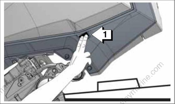
- Press and hold for at least three seconds, both the up and down trim buttons
Check your adjustment — tilt the outboard fully and adjust further, if necessary. Check after each adjustment.
To change or clear this setting, tilt the engine to the full down position.
Then, simultaneously press and hold for at least three seconds, both the up and down trim buttons.
Diagnostic Software Method
Your Dealer must use Evinrude Diagnostic soft ware v 6.1 or higher to limit maximum tilt-up.
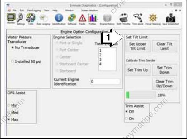
Check your adjustment — tilt the outboard fully and adjust further, if necessary. Check after each adjustment.
Repeat this procedure until the tilt limit stops the outboard's upward travel before it contacts the motor well.
Trim Gauge Calibration
Observe the trim gauge. If needed, use Evinrude Diagnostics software v 6.1 or higher to calibrate the upper and lower trim range of the gauge.
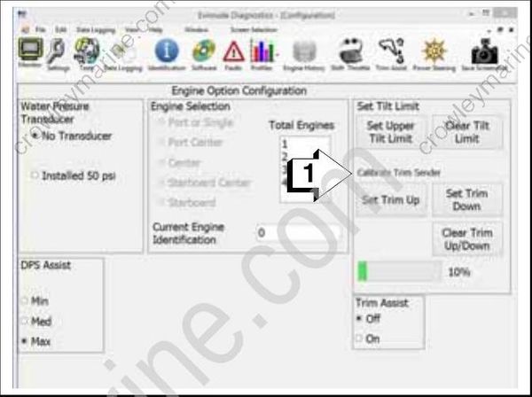
i-Trim
Evinrude E-TEC G2 outboards are equipped with i-Trim, an automatic trim-assist feature. By default, this feature is disabled from the factory.
Use the Evinrude ICON-Touch or ICON CS digital display to enable i-Trim. If the boat is not equipped with an ICON digital display, use the Configuration screen of Evinrude Diagnostics software v 6.1 or higher to enable trim assist.
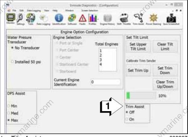
- Trim Assist
To activate the i-Trim:
- the key switch must be in the ON position
- use the trim/tilt switch to trim the engine to the full DOWN position.
During operation, the outboard will automatically trim up or down to an acceptable trim angle based on pre-programmed parameters.
Use the trim/tilt switch on the control lever to fine tune to an optimum trim angle.
IMPORTANT: Use of the trim/tilt switch to manually adjust the outboard trim angle will temporarily deactivate i-Trim.
To reactivate i-Trim:
- use the trim/tilt switch to trim the engine to the full down position
- bring the engine to idle speed.
Dynamic Power Steering (DPS)
The DPS system of AFA and newer outboards REQUIRES calibration when:
● installing multiple outboards (initial installation)
● replacing a DPS module
● replacing a steering pressure sensor
● replacing a steering position sensor
Failure to complete DPS system calibration can result in damage to the tie bar(s) and/or the transom of the boat due to overloading. Refer to DPS System Calibration on p. 309.
Most Evinrude E-TEC G2 models are equipped with Dynamic Power Steering (DPS). DPS offers three power steering assist levels.
Power Steering Assist Levels
Selection of power steering assist level is operator preference.
Be aware that changing the power steering assist level can affect boat handling.
After changing the level of power steering assist, operate the boat with care to become familiar with any changes in boat handling characteristics.
IMPORTANT: At engine speeds below 4500 RPM, ALL power steering assist levels provide the same rate of assist.
As engine speed increases above 4500 RPM, assist levels progressively decrease.
The factory default assist level is “Minimum”. Use the Evinrude ICON-Touch or ICON CS digital display to change the power steering assist level.
Refer to the Evinrude ICON-Touch or ICON CS user’s guide.
If the boat is not equipped with an ICON digital display, use the Configuration screen of Evinrude Diagnostics software v 6.1 or higher to change the power steering assist level.
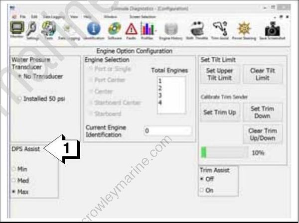
- DPS Assist
Multiple Outboard Alignment
Multiple outboard installations using AFA and newer outboards REQUIRE steering position sensor calibration.
Refer to Steering Position Sensor Calibration (AFA and Newer Models Only) on p. 310.
Failure to complete steering sensor calibration on multiple engine applications can result in damage to the tie bar(s) and/or the transom of the boat due to overloading.
Multiple outboards must be connected with a tie bar and adjusted to align the outboards for correct water flow to the gearcases and propellers.
Incorrect outboard alignment could cause one or more of the following:
- Propeller ventilation
- Reduction of top speed
- Improper boat tracking
- Engine overheat and powerhead damage
Follow the instructions provided by the tie-bar manufacturer for tie bar installation and adjustment.
Measure Alignment
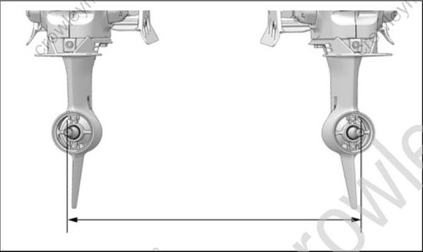
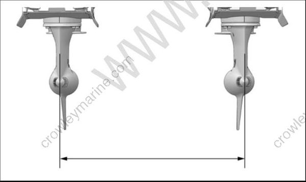
The “toe-in” (gearcase leading edges closer together than propeller shaft centers) or “toe-out” (gearcase leading edges farther apart than propeller shaft centers) is determined as follows:
- Position outboards straight with the anti-ventilation plates parallel with the bottom of the boat.
- Measure between propeller shaft centers.
- Measure between leading edges of gearcase.
Alignment Adjustment
Various boat/motor combinations respond differently to dual-outboard alignments. Each application must be thoroughly tested until the ideal combination of performance, steering, and cooling is found.
A common practice is to set-up the outboards parallel, or with a small amount of “toe-out,” and adjust inward until best results are achieved.
- A typical set-up, with outboards mounted directly on the transom, often runs best with a slight amount of “toe-in.”
- Outboards mounted behind the transom on motor brackets usually require parallel alignment or “toe-out.”
Adjust the outboard alignments by adjusting tie bar. Follow the tie bar manufacturer’s adjustment procedures.
Check steering operation. Make sure that the steering system operates properly at various trim angles.
Confirm Alignment
To confirm proper alignment, perform the following steps:
- Water test the boat.
- Monitor the water pressure for both outboards.
- Run the boat at various trim angles.
- Perform steering maneuvers and vary the throttle settings.
- Monitor boat and outboard performance.
A sudden loss of water pressure or excessive propeller ventilation on one or both outboards may indicate a misalignment of the gearcases. Reset the outboard alignment and retest
