

Ignition System
DANGER The electrical system presents a serious shock hazard. Allow outboard to sit for two minutes after running before handling capacitor or 55 V electrical components. Failure to handle capacitor properly can result in uncontrolled electrical discharge and possible electrical shock to humans. DO NOT handle primary or secondary ignition components while outboard is running or flywheel is turning.
Use the Evinrude Diagnostics software to check for fault codes before troubleshooting. Correct any problems and clear the codes FIRST.
Required Systems
Following is a complete list of circuits required for ignition output:
Stop Circuit
- Black/yellow wire NOT grounded (emergency stop switch lanyard in place).
Battery
- Battery switched B+ input to power up EMM
- Battery B+ input to Start Assist Circuit (SAC) of EMM
Stator Output Voltage
- Provides A/C voltage to EMM J2 connector: Outboard cranking, typical range is 20-40 VAC (AC output voltage is related to cranking RPM); Outboard running approximately 55 VAC.
EMM
- Controls ignition activation, injector activation, and ignition timing.
- Start Assist Circuit (SAC) converts battery volt age (12 V) to 30 V for system circuit (55 V).
Crankshaft Position Sensor
- Provides EMM with input.
- Outboard cranking speed exceeds 75 RPM and a steady CPS signal is generated.
Alternator Output/System Voltage
- System voltage from EMM (white/red) provides 55 VDC to the oil pumps, fuel injectors, and the ignition circuits of EMM.
Capacitor
- Connected to 55 V circuit (white/red) to stabilize current on 55 V circuit
- Negative terminal of capacitor must be grounded.
Ignition Coil
- Primary circuits are powered by system (55 V) voltage
- EMM provides control signal to ignition coil
- Output from ignition coil secondary winding and high tension spark plug wire.
Ignition System Circuit Diagram
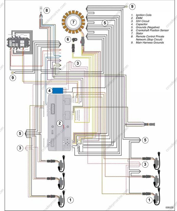
- Ignition Coils
- EMM
- 55V Circuit
- Capacitor
- Grounds (Negative)
- Crankshaft Position Sensor
- Stator
- Remote Control Private Network (Stop Circuit)
- Main Harness Grounds
Wiring Inspection
Visually inspect all wiring, connections, and grounds.
Use a digital ohmmeter to test resistance on all ground circuits and connections. Ohmmeter readings should be approximately 0.0 Ω.
Check that all engine wire harness grounds have continuity to the cylinder/crankcase. Ground Circuits on p. 115.
Clean or repair all ground circuits, wiring, and connections as needed.
Ignition System Tests
Use appropriate test leads or adapters such as Test Probe Kit, P/N 342677, when performing electrical tests.
NEVER pierce the insulation of the engine wiring, or use any piercing-style test probe. Piercing insulation damages the wire and can cause other unintended electrical problems.
Before continuing make sure the CPS is operating. Refer to Crankshaft Position Sensor (CPS) Operation Test on p. 117. If the Monitor screen says “Check CPS Sync,” refer to Crankshaft Position Sensor (CPS) Resistance Test on p. 117.
System Voltage Test
The ignition system is powered by the 55 V system.
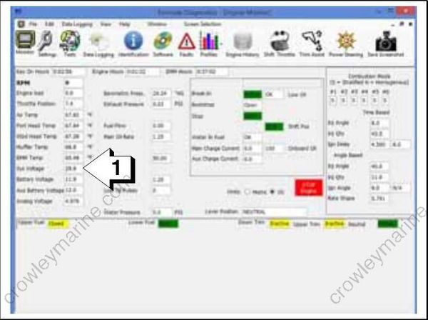
Engine Monitor Screen, System Voltage Display
Results:
• EMM ON (not running): 30 V ± 2, system voltage is GOOD.
• EMM ON (not running): less than 30 V ± 2, check 12 V power to EMM. Repair connection or wiring. Possible fault in EMM SAC circuit.
• RUNNING: 55 V ± 2, system voltage is GOOD.
• RUNNING: less than 55 V ± 2, check stator output to EMM. Repair connection or wiring. Possible faulty stator or EMM. Refer to Stator Tests on p. 125.
IMPORTANT: The EMM must be ON for voltage to be present on the system voltage (55 V) circuit. Power is normally supplied to the EMM when the key switch is turned ON. The EMM is also turned ON when it begins to receive AC voltage from the stator while the outboard is being cranked.
Running Ignition Tests
Use Evinrude Diagnostics software to monitor system voltage (55 V).
• Voltage readings at a specific speed (RPM) should be steady.
• Refer to System Voltage Test on p. 122.
Use an inductive timing light to monitor the spark signal through each of the secondary circuit (spark plug lead) wires.
Start outboard and observe timing light strobe. Look for a consistent flash and only one flash per revolution. The strobe of the timing light should be the same for each cylinder.
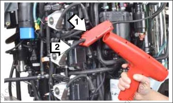
- Timing light pick-up
- Spark plug lead
Results:
Steady voltage and strobe, engine misfires:
- Inspect or replace spark plugs
- Refer to Static Tests on p. 105.
- Check for internal engine damage.
Steady voltage, erratic strobe, engine misfires:
• Inspect or replace spark plugs
• Check CPS resistance.
• Refer to Ignition Circuit Tests on p. 123.
• Refer to Ignition Coil Tests on p. 123.
Voltages fluctuate, engine misfires:
Inspect battery and connections
• Test capacitor and all ground connections.
• Refer to System Voltage Test on p. 122
• Refer to Ignition Circuit Tests on p. 123.
• Refer to Ignition Coil Tests on p. 123.
IMPORTANT: If a running problem occurs at about 1200 RPM, the outboard may be in S.A.F.E. Refer to S.A.F.E. on p. 89.
Ignition Coil Tests
There are no ignition coil tests available. Before replacing an ignition coil, be sure:
• 55 V is supplied to the white/red wire of the ignition coil connector.
• A control signal is present on the orange wire of the ignition coil connector. Refer to Ignition Circuit Tests on p. 123.
• The black wire of the ignition coil connector provides continuity to ground.
• The secondary spark plug lead provides continuity.
If all of the above tests are good, and a cylinder does not have spark, replace the ignition coil with a known good coil.
Ignition Circuit Tests
Ignition 55V Circuit Voltage Test
Use a digital multimeter calibrated to a scale that reads 55 V (DC) to measure voltage between the ignition coil electrical connector and engine ground.
Disconnect ignition coil connector.
Connect negative meter lead to ground. Use an appropriate test probe lead to connect positive meter lead to pin 3 (white/red wire) of engine harness electrical connector.
Turn the key switch to the ON position. Observe voltage at pin 3.
- Voltage should be approximately 30 V.
Start the engine. Observe voltage at pin 3.
- The voltage at pin 3 should be approximately 55 V.
This will result in an Ignition Coil OPEN Circuit fault code.
Results:
• No voltage reading, confirm 55V Circuit Resistance. Refer to Ignition 55V Circuit Resistance Test on p. 123.
• No voltage reading, refer to System Voltage Test on p. 122.
Ignition 55V Circuit Resistance Test
Disconnect the electrical connector from the ignition coil.
Use a digital multimeter with appropriate test probe leads to measure the resistance of the 55V circuit.
Make sure the key switch is in the OFF position. Connect the positive meter lead to the engine harness connector wire listed in the table.
Connect the negative meter lead to the red/white wire of a known good circuit such as a fuel injector.
| Ignition 55V Circuit Resistance | ||
|---|---|---|
| Wire | Pin | Result |
| WHITE/RED | 3 | < 1 Ω |
Results:
- An infinite reading (∞) indicates an open circuit.
Isolate the faulty component. Check wiring and connections. Repair or replace faulty wiring.
Ignition Ground Circuit Resistance Test
Use a digital multimeter with appropriate test probe leads to measure the ground circuit resistance.
Make sure the key switch is in the OFF position. Connect the positive meter lead to the engine harness connector wire listed in the table. Connect the negative meter lead to engine ground.
| Ignition Ground Circuit Resistance | ||
|---|---|---|
| Wire | Pin | Result |
| BLACK | 1 | < 1 Ω |
Results:
- An infinite reading (∞) indicates an open circuit. Isolate the faulty component. Check wiring and connections. Repair or replace faulty wiring.
Ignition Control Circuit Voltage Test
Disconnect the electrical connector from the ignition coil.
Use a digital multimeter with appropriate test probe leads to measure signal circuit voltage.
Connect the positive meter lead to the engine harness connector wire listed in the table. Connect the negative meter lead to engine ground. Turn the key switch to the ON position.
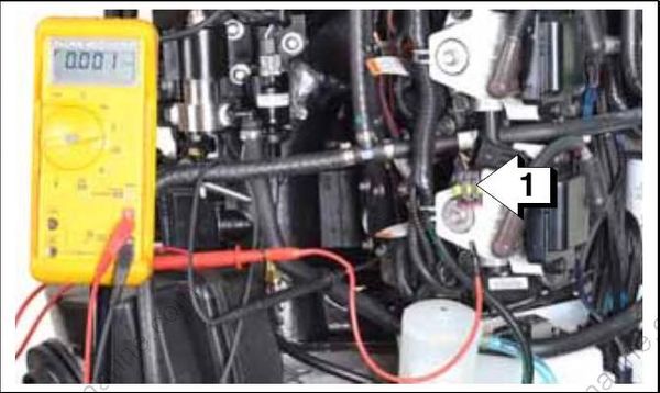
- Engine harness connector (ignition coil)
| Ignition Circuit Voltage | ||
|---|---|---|
| Wire | Pin | Result |
| ORANGE/BLUE(upper cylinder) | 2 | 5 to 7 VDC |
| ORANGE/PURPLE(middle cylinder) | 2 | 5 to 7 VDC |
| ORANGE/GREEN(lower cylinder) | 2 | 5 to 7 VDC |
Capacitor Test
IMPORTANT: Make sure the capacitor is discharged before testing.
Disconnect the capacitor from electrical harness.
Use an ohmmeter set on the high ohms scale to test the capacitor. Connect the meter leads to the capacitor terminals:
- If the capacitor is working correctly, it will store energy from the meter. The resistance reading will increase until it goes to (nearly) infinity.
- If the capacitor is shorted, the reading will immediately show full continuity.
- If there is an open circuit in the capacitor, the meter will show no continuity.
If the resistance reading starts as a negative number, or the reading goes down in value, the capacitor already retains some stored energy. Ground the capacitor and test again.
