

Step 1: Cooling System
Overcooling: Debris may prevent the valve from closing completely.
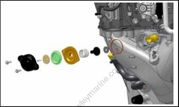
Pressure Relief Valve
Step 2: Thermostats
Thermostats control water flow and operating temperature at lower speeds (below 2500 RPM).
Overheating: A restricted or faulty thermostat typically results in LOW SPEED overheating.
Overcooling: Debris may prevent the thermostat from closing completely.
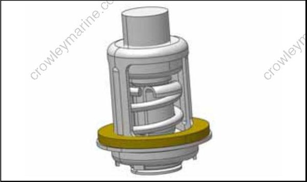
Thermostat
Step 3: Block Venting
A fitting and hose from the top of the exhaust manifold on the cylinder block allows the constant movement of water and/or air from the block. Circulated water flows through a hose and tee-fitting, exiting through the overboard indicator.
Step 4: Operation
All models use a two-stage cooling system design. The cooling system is dependent on water pump pressure and controlled by thermostat and pressure valve operation.
Restricted or inadequate water flow through the outboard reduces cooling system performance and may lead to severe powerhead damage.
Cylinder Block / Cylinder Head Cooling
The flow of water through the cooling system is controlled by two thermostats and one pressure valve. The pressure valve is connected by hoses to the top of each cylinder head.
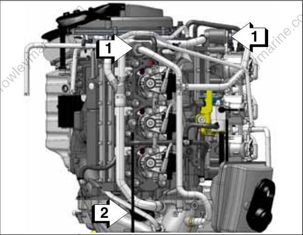
- Thermostats
- Pressure valve assembly
The thermostats and pressure valve control the flow of water leaving the water passages of the cylinder heads.
At low speed,, the pressure valve is closed and the thermostats regulate water to flow to maintain a temperature of approximately 143°F (62°C).
Water from the thermostat flows out of the cylinder heads through a hose, to the exhaust adapter, exhaust housing and then out of the outboard.
At higher speeds,, water pressure opens the pressure valve at approximately 2500 to 3000 RPM. Water bypasses the thermostats and then flows through the pressure valve. Water from the pressure valve flows through internal passages of the exhaust adapter to the exhaust housing and then exits through the gearcase water outlets.
This pressure controlled water outlet circuit provides a high flow rate of discharge water during high speed operation.
EMM and Vapor Separator Cooling
Cooling water is routed from the top of the cylinder block, through a water filter to the inlet fitting of the EMM water cavity. Cooling of the EMM helps to stabilize the temperatures of internal components.
IMPORTANT: Improper EMM cooling will activate fault codes 25 and 29 and the Engine Monitor warning system. Refer to the EMM Fault Code Chart at the back of this manual for specific fault code information.
Cooling water from the EMM is routed to the water inlet fitting of the vapor separator water cavity. Cooling the vapor separator fuel chamber minimizes fuel vaporization.
Cooling water from the vapor separator is routed to the overboard indicator.
Step 5: Engine Temperature Check
IMPORTANT: The engine temperatures listed in this section are based on an intake water temperature of 70° ± 10°F (21° ± 3°C).
Install correct test propeller and place outboard in a test tank or in the water. Start outboard and run at 3000 RPM in FORWARD gear for at least five minutes. Remember, running outboards at high speeds in test tanks may disrupt water flow to gearcase water intakes. Make sure the outboard has adequate water flow.
When servicing the propeller, always shift the outboard to NEUTRAL position, turn the key switch OFF and remove the key, so the outboard cannot be started accidentally.
Reduce speed to IDLE for five minutes. Check IDLE operating temperature.
Increase speed to 5000 RPM and check temperature.
Check temperature on both sides of powerhead.
If engine temperature is not within range, troubleshoot cooling system.
