

Cooling System
At low speed, the pressure valve is closed and the thermostats regulate water to flow to maintain a temperature of approximately 143°F (62°C).
Water from the thermostat flows out of the cylinder heads through a hose, to the exhaust adapter, exhaust housing and then out of the outboard.
At higher speeds, water pressure opens the pressure valve at approximately 2500 to 3000 RPM. Water bypasses the thermostats and then flows through the pressure valve. Water from the pressure valve flows through internal passages of the exhaust adapter to the exhaust housing and then exits through the gearcase water outlets.
This pressure controlled water outlet circuit pro vides a high flow rate of discharge water during high speed operation.
EMM and Vapor Separator Cooling
Cooling water is routed from the top of the cylinder block, through a water filter to the inlet fitting of the EMM water cavity. Cooling of the EMM helps to stabilize the temperatures of internal components.
IMPORTANT: Improper EMM cooling will activate fault codes 25 and 29 and the Engine Monitor warning system. Refer to the EMM Fault Code Chart at the back of this manual for specific fault code information.
Cooling water from the EMM is routed to the water inlet fitting of the vapor separator water cavity. Cooling the vapor separator fuel chamber minimizes fuel vaporization.
Cooling water from the vapor separator is routed to the overboard indicator.
Engine Temperature Check
IMPORTANT: The engine temperatures listed in this section are based on an intake water temperature of 70° ± 10°F (21° ± 3°C).
Install correct test propeller and place outboard in a test tank or in the water. Start outboard and run at 3000 RPM in FORWARD gear for at least five minutes. Remember, running outboards at high speeds in test tanks may disrupt water flow to gearcase water intakes. Make sure the outboard has adequate water flow.
When servicing the propeller, always shift the outboard to NEUTRAL position, turn the key switch OFF and remove the key, so the outboard cannot be started accidentally.
Reduce speed to IDLE for five minutes. Check IDLE operating temperature.
Increase speed to 5000 RPM and check temperature.
Check temperature on both sides of powerhead.
If engine temperature is not within range, trouble shoot cooling system.
Software Method
Use the Monitor screen of Evinrude Diagnostics software v 6.1 or higher, to read temperature displays.
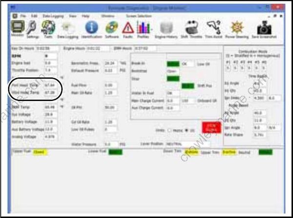
Engine Monitor Screen
Typical temperature displays at IDLE speed should be 140°F ± 10°F (60°C ± 6°C)
Typical temperature displays at WOT speed should be 150°F ± 10°F (66°C ± 6°C)
Operating temperature must not exceed 203°F (95°C).
Pyrometer Method
Use a Temperature Gun, P/N 772018, or a digital pyrometer to measure the outboard’s operating temperatures.
Measure temperature at the top of cylinder block, next to the thermostat housing and cylinder head. Check temperature on both sides of powerhead.
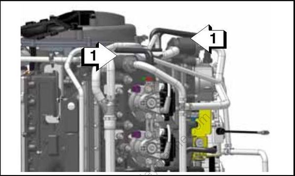
- Top of cylinder block
Typical pyrometer readings at IDLE speed should be 140°F ± 10°F (60°C ± 6°C)
IMPORTANT: If you get low or inaccurate readings with a digital pyrometer, coat the probe location with Thermal Joint Compound, P/N 322170.
Idle Operating Temperature Troubleshooting (Below Range)
If engine IDLE temperature is below operating range 140°F ± 10°F (60°C ± 6°C), check thermostat and pressure relief valve operation.
Pressure Relief Valve
The pressure relief valve should be closed at IDLE speed. Water should not flow past the plunger and the sealing surface in the exhaust adapter.
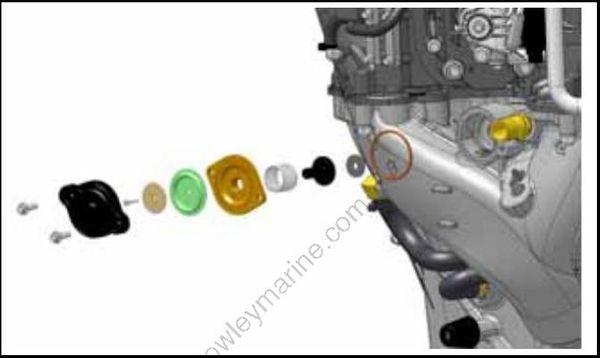
Pressure Relief Valve
Start the outboard and check IDLE operating temperature.
If IDLE temperature is too low, pinch off the water hose from the cylinder heads to the pressure relief valve.
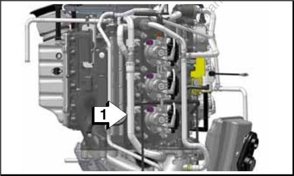
- Outlet hose
Use hose pinching pliers (acquired through local tool source) to prevent hose damage.
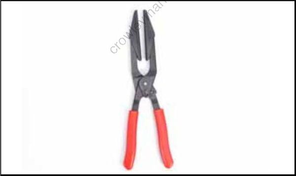
Hose Pinching Pliers
Start the outboard and check IDLE operating temperature using Evinrude Diagnostics software, v 6.1 or higher.
If IDLE temperature increases to specific operating range, 140°F ± 10°F (60°C ± 6°C), after pinching off hoses and eliminating water flow to the pressure relief valve, the pressure relief valve is leaking. Clean or replace the pressure relief valve as needed.
If IDLE temperature is still below operating range with hoses pinched off, inspect thermostats and thermostat seals.
Thermostats
Remove thermostat cover(s) and inspect thermostat(s).
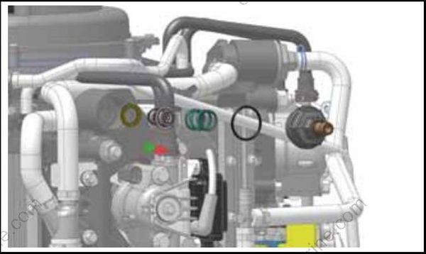
Check position of thermostat seal and how thermostat seals against cylinder head. Seal must be properly fitted to flange of thermostat.
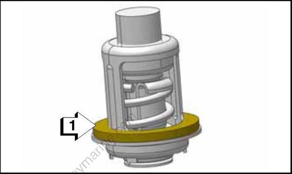
- Seal, thermostat
Check thermostat for cracks, heat damage, or signs of corrosion. Check for proper operation. Thermostat opens at 143°F (62°C).
