

Components
The ICON II remote control system includes the following components:
• ICON II remote control(s)
• Remote control (private) network
• NMEA 2000 network
• Up to four Evinrude E-TEC G2 74° V6 outboards.

Typical Installation
Single outboard system with single lever binnacle remote control shown
ICON II Remote Control
ICON II remote controls are electronic shift and throttle remote control systems which manage all
engine control functions through a low-voltage, digital data network. Sensor inputs and internal EMM controllers are used to control the operation of the outboard’s shift and throttle functions.
Use Evinrude Diagnostics software to troubleshoot the sensors. Refer to the Fault Code Chart for a complete list of all control system fault codes.
ICON II remote controls are available in the following configurations:
• Single Lever Binnacle Mount, use in single outboard, single or dual station installations
• Concealed Side Mount, use in single outboard installations. May be used with an optional accessory foot throttle.
• Dual Lever Binnacle Mount, use in multiple outboard (up to 4), single or dual station installations.
Remote Control (Private) Network
Shift and throttle information is transmitted and received between the EMM and ICON II remote
control system via a dedicated Controller Area Network (CANbus), known as the remote control network, or private network. The remote control network is powered directly from the battery. The network may include backbone buss cables, backbone extension cables, one or more 6-port hubs, or accessories. Refer to the Evinrude E-TEC G2 Installation and Pre delivery Guide.
NMEA 2000 Network
For safety, the remote control data is also shared on a NMEA 2000 network as backup.
Outboard EMM
The EMM receives shift, throttle and other control information from the ICON II remote control.
Shift and throttle controllers internal to the EMM activate the shift actuator and the electronic throttle body assembly to the positions commanded by the remote control. Also see Electronic Shift
Controller on p. 88 and Electronic Throttle Controller on p. 86. If the ICON II remote control cannot communicate with the EMM, all remote control LED indicators flash until control levers and shift actuators are in NEUTRAL. Then, the NEUTRAL indicator LED for the outboard that has a fault flashes. The EMM:
| Activates NEUTRAL idle mode |
|---|
| Stores remote control fault codes: 21, 24, 27, or 30 |
Shift Actuator
The shift actuator converts electronic signals from the Electronic Shift Controller (ESC) in the EMM into the mechanical motion required to shift the outboard into and out of gear. Also see Shift Actuator on p. 421.
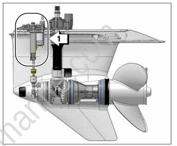
- Shift actuator
If the shift actuator cannot achieve the commanded gear, the FORWARD, NEUTRAL or REVERSE indicator LED flashes to indicate which gear position is affected. The EMM:
| Activates S.A.F.E . |
|---|
| Stores EMM fault code 204 |
| Engine Monitor: CHECK ENGINE display ON |
The outboard will shutdown if NEUTRAL cannot be achieved.
Throttle Valve Assembly
The electronic throttle body assembly converts electronic signals sent from the Electronic Throttle Controller (ETC) in the EMM into the mechanical motion required to move the throttle plate. Also see Electronic Throttle Controller on p. 86
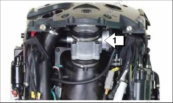
- Throttle valve assembly
If the ETC cannot communicate with the electronic throttle body for more than 250 milliseconds, the EMM:
| Activates S.A.F.E |
|---|
| Stores EMM fault code 162 |
| Engine Monitor: CHECK ENGINE display ON |
If the throttle plate cannot achieve the commanded position, the EMM:
| Activates S.A.F.E. |
|---|
| Stores EMM fault code 179 |
| Engine Monitor: CHECK ENGINE display ON |
System Settings and Diagnostics
Use Evinrude Diagnostic software, v 6.1 or higher to communicate with the remote control. Refer to
Communication on p. 92. Diagnostic software can change configuration settings, view identification information and stored faults, monitor control functions or update software.
Multiple Engine Instancing
Multiple outboard installations require the transom position of each outboard be identified.
Engine identity is set and stored in the EMM of each outboard. By default the EMM of all outboards is set to instance zero (0) at the factory. Outboards are identified as Instance 0 through 3,
from port to starboard, up to four outboards. Engine identity of each outboard must be set manually or with Evinrude Diagnostics software v 6.1 or higher. Use the following chart to assign the engine instance number to the outboard’s position on the transom.
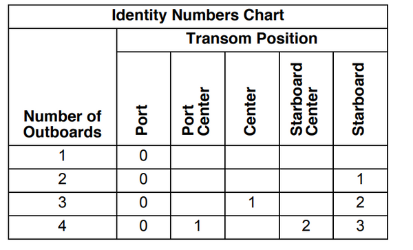
If duplicate engine identity numbers are detected, the affected outboard’s NEUTRAL indicator LED
will flash rapidly.
