

Compression Testing
Start and run outboard until it achieves operating temperature, then shut OFF.
Disconnect crankshaft position sensor (CPS) connector. Remove all spark plugs.
Install compression tester’s hose attachment into spark plug hole (14 mm threads).
Turn the key switch to the ON position.
While cranking outboard with starter, note maxi mum pressure reading on gauge. Repeat procedure for each cylinder.
If engine shows a variation greater than 15 psi (100 kPa) between cylinders, check for:
• damaged cylinder head
• damaged pistons
• broken or stuck piston rings
• scored cylinder walls
Return throttle to idle position and reconnect CPS connector. Replace spark plugs.
Powerhead Removal
Protect against hazardous fuel spray. Before starting any fuel system service, carefully relieve fuel system pressure. Refer to Relieving Fuel System Pressure on p. 168. To prevent accidental starting while servicing, twist and remove spark plug leads.
Procedure
IMPORTANT: Before removing the powerhead trim the engine to the vertical position.
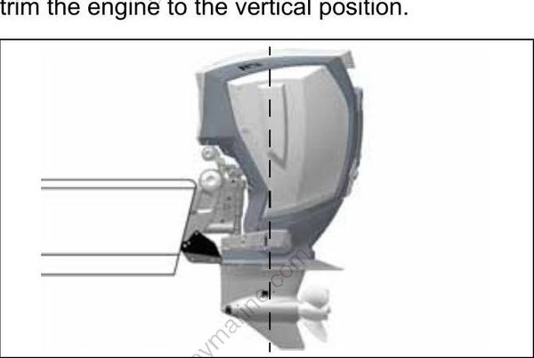
Engine in Vertical Position 009167
Remove the top engine cover. Then remove the 4 inch plug from the center frame. Next remove the 3.5 inch plug from the air duct and the thread protector from the flywheel threads.
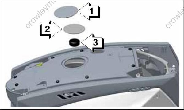
- 4 inch plug 009168
- 3.5 inch plug
- Thread protector
Remove the front cover. Then disconnect all cables, buss cables and hoses from the engine.
Remove the rear cover, starboard and port frames and front frame. Refer to Engine Cover and
Frame Service on p. 55.
Remove the rigging grommets from the power head.
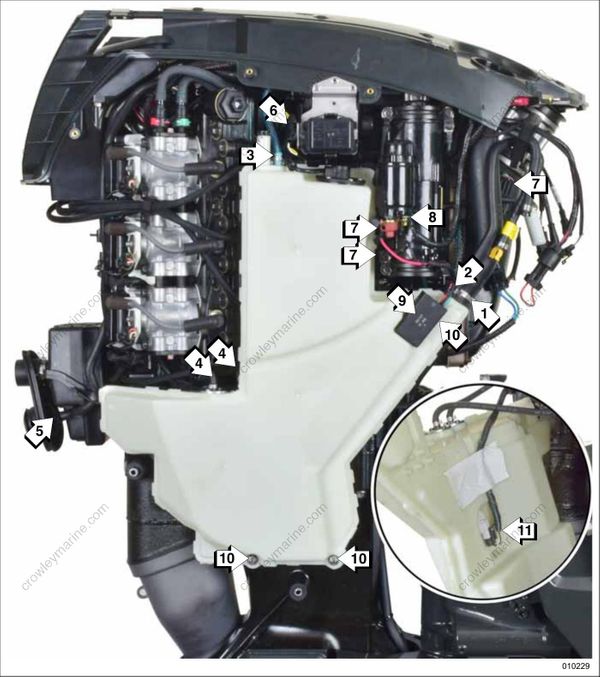
Starboard
Remove the following hose clamps and hoses:
Oil fill hose (lower), remove the hose from the oil tank. 2. Remote oil fill hose, remove the hose from the oil tank. 3. Oil tank vent hose, remove the hose from the oil tank.
Two oil supply hoses, remove the hoses from the oil pick ups.
Depending on the orientation of the clamps it may be necessary to remove these hose clamps and hoses at step 11.
Overboard indicator hose, remove the hose from the grommet. Disconnect the following electrical connectors: 6. Oil level sender (oil tank).
Trim relay, three Amp connectors and two 2 ring terminals (1 {ground} on the lower starter mounting bracket and 1 {B+} on the starter solenoid).
Starter solenoid (small ring terminal). Remove the following:
The trim relay from the oil tank.
10.The three nuts and washers retaining the oil tank.
11.Remove the oil tank, then disconnect the electrical connector from the LOW oil switch.
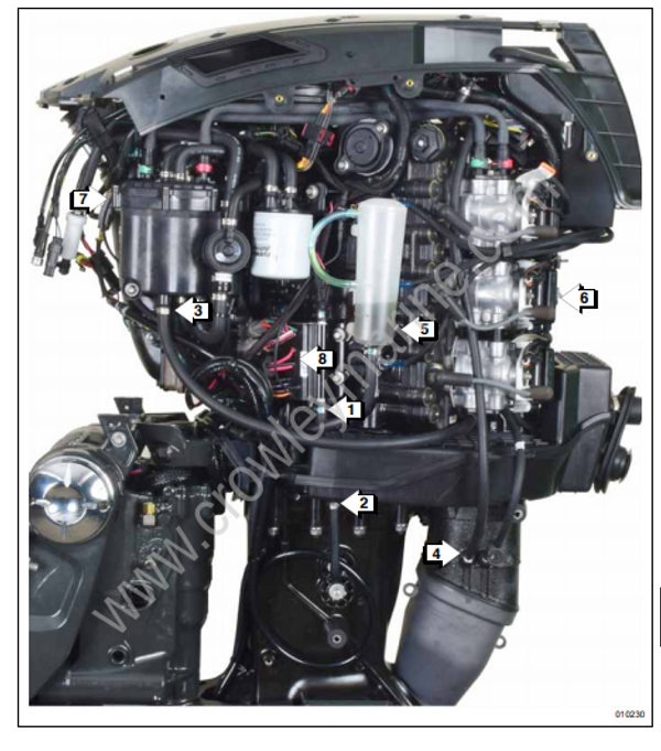
Port
Remove the following hose clamps and hoses:
- Hose, DPS module to exhaust adapter, remove hose from the DPS module.
- Hose, muffler drain to adapter, remove the hose from the muffler fitting.
- Hose, block to vapor separator, remove the hose from the vapor separator.
- Hose, exhaust back pressure, remove the hose from adapter fitting.
- Hose, Gearcase to oil reservoir, remove the hose from oil reservoir.
Disconnect the electrical connectors from the following: - Exhaust temperature sensor
- Shift actuator
- DPS module (5)
Lifting the Powerhead
To avoid personal injury, make sure the lifting capacity of the hoist is at least twice the weight of the outboard. DO NOT allow the lift hook or chain from the hoist to come in contact with any part of the engine during lifting.
Use Engine Lifting Fixture, P/N 357667, to lift the powerhead from the adapter. Use the centerline lifting eye to lift the complete engine. Use the off set lifting eye to remove and install the power head, or to support the engine and remove and install the stern and swivel bracket assembly.
IMPORTANT: Carefully thread the lifting fixture into the threads of the flywheel at least 6 complete turns. Do NOT cross-thread the threads of the lifting fixture into the threads of the flywheel.
Install the lifting fixture completely into the fly wheel. If needed, turn the flywheel until the lifting rings of the fixture are aligned front to back as shown.
Make sure the off-set lifting eye is to the REAR of the engine. Fasten appropriate chain hook to the off-set lifting eye.
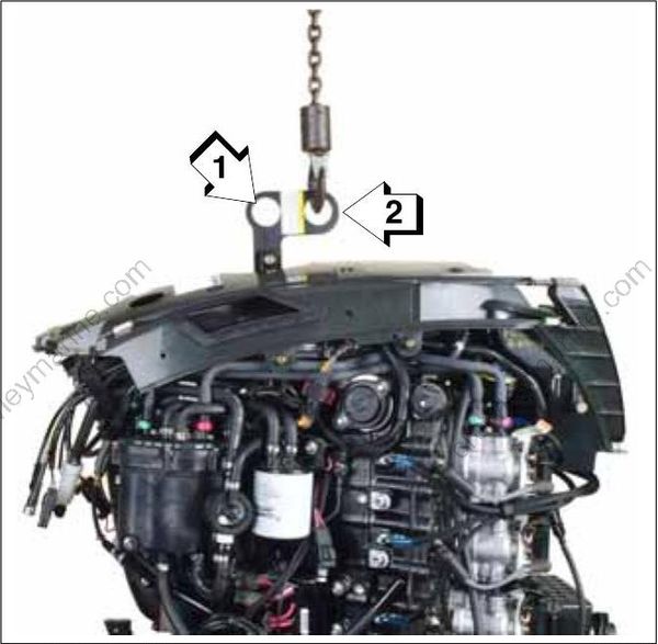
- Centerline lifting eye
- Off-set lifting eye (to REAR of engine)
010224
Remove the 12 nuts and washers retaining the powerhead to the exhaust adapter and exhaust housing.
On the port side, there are five nuts and washers on the exhaust housing and two nuts and washers on the exhaust adapter.
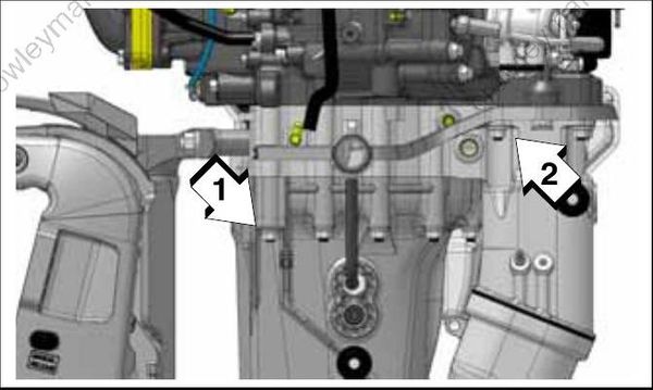
Port 010225
- Five nuts and washers on the exhaust housing
- Four nuts and washers on the exhaust adapter
On the starboard side, there are three nuts and washers on the exhaust housing and three nuts and washers on the exhaust adapter.
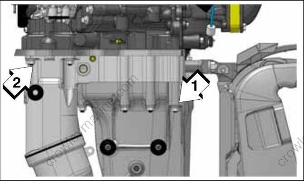
Starboard 010226
- Three nuts and washers on the exhaust housing
- Three nuts and washers on the exhaust adapter
Carefully lift the powerhead from the exhaust adapter. The powerhead should lift easily. If the powerhead does not lift easily, check for any fasteners or hose connections that may have been overlooked during the removal procedures.
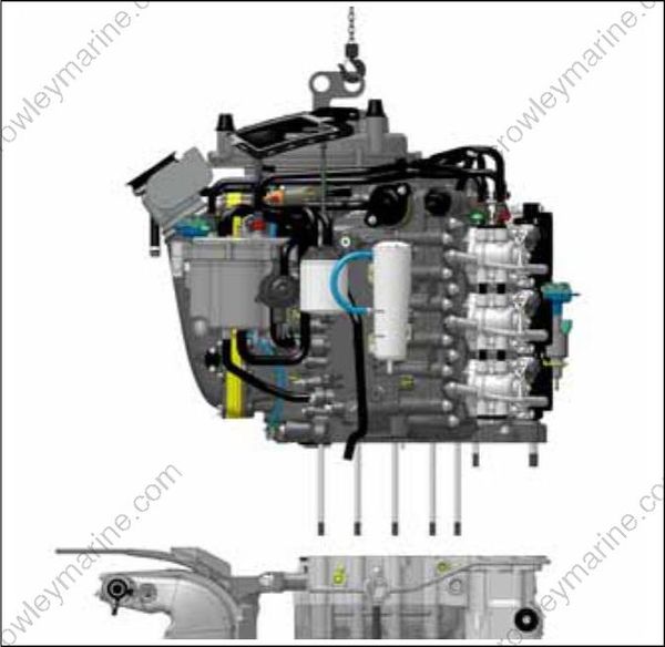
010227
Remove the old o rings from the exhaust adapter.
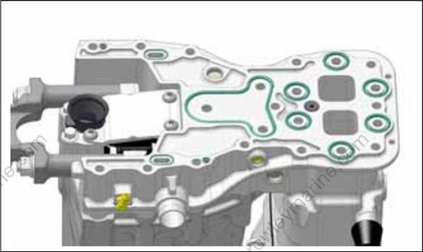
O-Rings 010228
Clean the adapter with solvent.
To avoid personal injury, make sure the capacity of the engine stand is at least twice the weight of the outboard.
Secure the powerhead in a suitable engine stand.
Powerhead Disassembly
Systems Removal
To simplify reassembly and wiring installation, lay out the various screws and clamps in the order of their proper location.
Remove the center frame, EMM and engine harness as an assembly. Refer to Center Frame
Removal on p. 67.
Remove the ignition coil brackets and ignition coils. Refer to Ignition Coil Servicing on p. 135.
Remove fuel pump assemblies, fuel filter housing, fuel rails, and injectors. Refer to Fuel Component Servicing on p. 168.
IMPORTANT: Mark injectors for cylinder location before removal. All injectors must be installed in their original location. Improper injector installation can result in powerhead failure.
Remove the electric starter. Refer to Starter Removal on p. 138.
Remove the front and rear oil pumps and oil distribution hoses. Refer to Oil Component Servicing on p. 204.
Remove the cooling water hoses.
Remove the flywheel and stator. Refer to Flywheel and Stator Servicing on p. 133.
Remove the plenum and reed plate assemblies. Refer to Intake Manifold Service on p. 180.
