

SPECIALIZED TEST PROCEDURES
Contact with a rotating propeller is likely to result in serious injury or death. Assure the engine and prop area is clear of people and objects before starting engine or operating boat. Do not allow anyone near a propeller, even when the engine is off. Blades can be sharp and the propeller can continue to turn even after the engine is off. Remove propeller before servicing and when running the outboard on a flushing device. DO NOT run the engine indoors or without adequate ventilation or permit exhaust fumes to accumulate in confined areas. Engine exhaust contains carbon monoxide which, if inhaled, can cause serious brain damage or death.
The following tests are performed with the outboard running. Observe the operation of each electrical circuit. Look for inconsistencies between similar circuits and variations in cylinder performance.
Dynamic Tests
Use the diagnostic program to perform Dynamic Fuel and Ignition tests. These tests can be used to momentarily stop injector or ignition function for a
selected cylinder while the outboard is running. This is an effective tool for checking the performance of each cylinder. Comparing one cylinder’s performance to others can frequently isolate a cylinder that is not operating properly.
IMPORTANT: DO NOT misinterpret tests run at IDLE. The idle speed controller in the EMM compensates to maintain a constant engine speed at IDLE. The Dynamic Tests screen of the diagnostic software includes a function to temporarily disable the idle controller.
Dynamic Tests can be used in conjunction with:
A timing light to determine how other cylinders are affected by one cylinder being “dropped”; or
A voltmeter to check voltage changes on electrical circuits.
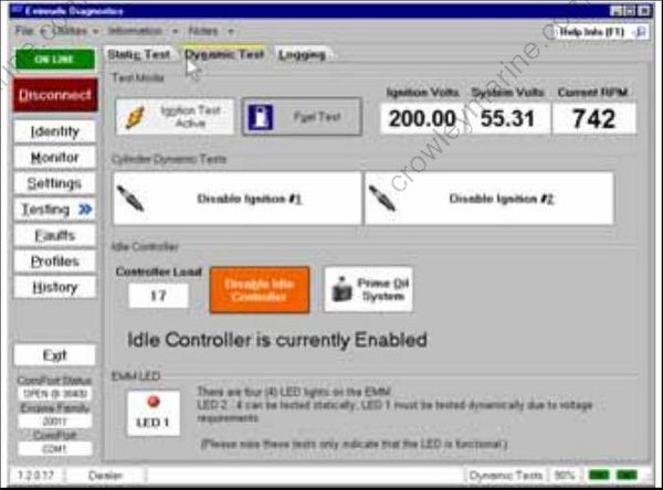
Dynamic Tests Screen
IMPORTANT: Test the outboard while the runability issue is present. Use the test procedures to identify inconsistencies in voltages and cylinder
performance. Once a circuit has been identified as malfunctioning, a thorough inspection of all related wiring and connections must be performed. Check all voltage inputs and grounds; and perform resistance tests for all circuits prior to replacing any suspect components.
Testing with Timing Light
The electrical system presents a serious shock hazard. DO NOT handle primary or secondary ignition components while outboard is running or flywheel is turning.
An inductive timing light can be used to monitor ignition system output and the activation of fuel injectors and the oil injection pump. DO NOT clamp timing light pick-up on more than one wire at a time. Avoid erratic timing light reading by isolating pick-up from other wires. Self powered timing lights offer the convenience of no power cables and can help eliminate false signals.
Ignition System Output
Use the timing light to monitor each spark plug lead for a consistent flash. The strobe should indicate one flash per revolution. Intermittent output
or multiple flashes per revolution indicate improper ignition control.
Test ignition system grounds, primary circuit resistance, and EMM output voltages prior to replacing any components.
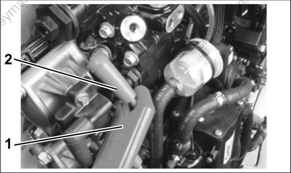
- Timing light pick-up
- Spark plug lead
Fuel Injector/Oil Injection Pump Activation
Use the timing light to monitor each fuel injector or the oil injector pump lead(s). The strobe of the light indicates current in the circuit.
Test all grounds, circuit resistance(s), and circuit voltages prior to replacing EMM for faulty injector
or pump control function.
Inductive Amp Meter Test
Use an inductive amp meter to monitor battery charging and current flow. Identifying erratic amperage in a circuit can be used to isolate a problem component.
Engine Monitoring Information
Use the Evinrude Diagnostics Software program to access the engine Monitor screen. This screen display provides engine information as it is occurring. Circuits are monitored for actual voltages or the condition of the circuit. Switch and sensor circuits, battery voltage (12 V), system voltage (55 V), and ignition voltage are continuously monitored.
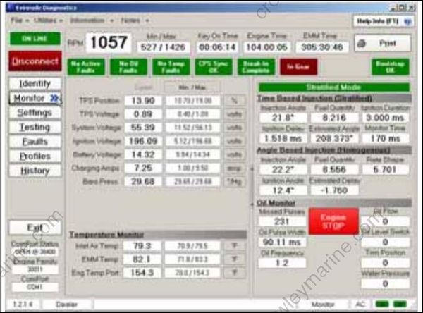
Engine Monitor Screen
IMPORTANT: The engine Monitor screen of the
diagnostics program does not offer voltage information for all circuits.
IMPORTANT: The engine Monitor screen of the diagnostics program does not offer voltage information for all circuits.
Voltage Testing
Use a digital multimeter to check voltages. Identify all wiring and circuits prior to performing any voltage tests. Refer to Wiring Diagrams and descriptions of the various systems for specific information on each circuit.
55 V Circuits
All 55 V circuits are supplied 12 V when the key switch is ON, the EMM is powered up, and the outboard is not running (electric start models).
Stator output supplies 55 VAC to the rectifier circuits of EMM once the outboard is running. The initial cranking voltage is 30 V or higher and
increases to 55 V when outboard is running.
Ignition Circuit
Ignition voltage displayed on the engine Monitor screen of the diagnostic software will have approximately 0.1 V when the key switch is ON, the EMM is powered up, and the outboard is not running (electric start models). This voltage increases to 130 V to 220 V with the outboard running.
Perform voltage tests on all related circuits and compare voltage readings. Check voltages while Dynamic Tests are activated.
Identify erratic or lower than expected voltage readings. Determine if the voltage source or the wiring and connections of the circuit are the problem.
START CIRCUIT
The start circuit provides the required current to the starter motor and associated electrical circuits.
Electric Starter Operation
The starter must engage and turn the flywheel. A minimum cranking speed of 300 RPM must be achieved for the outboard to start.
Optimum starter performance is achieved by providing:
Proper battery capacity (640CCA)
Cables capable of transferring the amperage
Low resistance battery and cable connections
A solenoid capable of switching the current
These “high amperage” start circuit components provide the battery current required to crank and start the outboard (electric start models). Check
the quality and condition of the following:
12 V Marine Battery
Battery type, capacity, and condition
Condition of battery posts, terminals, and connections
Battery switch type, capacity, and connections
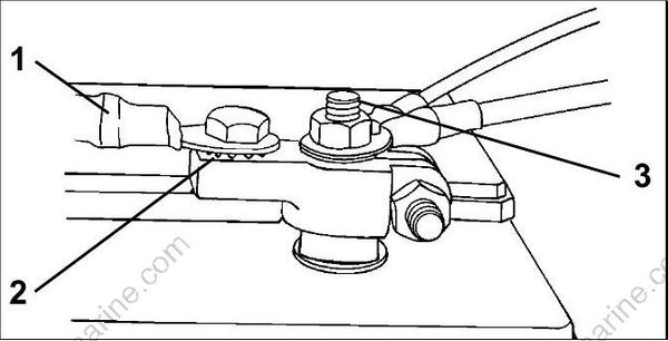
- Main battery cable
- Star washer
- Battery post
Refer to Battery Installation on p. 34 for battery, terminal, and cable requirements.
Starter Solenoid
Starter solenoid and connections
Starter solenoid ground, terminal “B”
Starter cable (solenoid to starter motor)
12 V from solenoid terminal (POS) and engine harness (red wire) to 10 A fuse
