

Step 1: FUEL COMPONENT SERVICING
Gasoline is extremely flammable and highly explosive under certain conditions. Use caution when working on any part of the fuel system.
Protect against hazardous fuel spray. Before starting any fuel system service, carefully relieve fuel system pressure. Refer to Relieving Fuel System Pressure.
Always disconnect the battery cables at the battery before servicing the fuel system unless instructed to do otherwise.
Always work in a well ventilated area and wipe off any fuel spillage.
DO NOT smoke and make certain no open flames or ignition sources exist.
After servicing the fuel system check for leaks. Failure to check for fuel leakage could allow a leak to go undetected, resulting in fire or explosion.
Relieving Fuel System Pressure
Protect against hazardous fuel spray. Before starting any fuel system service, carefully relieve fuel system pressure.
IMPORTANT: Minimize fuel system pressure prior to disassembly. Temporarily restrict the fuel supply hose from fuel tank with hose pincer, or disconnect the fuel supply hose on portable fuel tanks. Remove propeller and disconnect circulation fuel pump electrical connector. If outboard runs, start and run at IDLE for 5 seconds and STOP outboard. If outboard does NOT run, crank for 10 seconds.
Disconnect the battery cables at the battery.
Wrap a shop towel completely around the pressure test valve while connecting Fuel Pressure Gauge, P/N 5000902, to top test fitting of high pressure fuel pump/vapor separator assembly.

- Shop towel
Insert venting hose of gauge into a suitable container.
Slowly open gauge’s venting valve.
Clean up any spilled fuel with shop towels.

- Test fitting
- Venting valve
- Venting hose
Fuel Filter
Removal
Disconnect the battery cables at the battery.
Remove filter carefully to prevent spilling contents.
Inspect contents for any presence of water. If water is present, identify the source and correct the problem. Take additional fuel samples and drain fuel tank(s) if necessary.

- Fuel filter
- Arrow
Installation
Position filter in fuel supply hoses. Note arrow indicating direction of fuel flow on filter. Secure filter with appropriate clamps.
Squeeze primer bulb to prime fuel system. Hold pressure on bulb and check for fuel leaks.
Connect battery cables.
Run outboard and check for fuel leaks.
Fuel Lift Pump
The fuel lift pump is serviceable as a complete assembly or can be repaired with a fuel pump repair kit. Refer to appropriate parts catalog for service parts.
Removal
Disconnect the battery cables at the battery.
Remove air silencer and lower motor covers as needed.
Disconnect the fuel lift pump pulse hose at the crankcase fitting.

- Crankcase fitting
Disconnect the fuel supply hose at the in-line oil supply fitting.
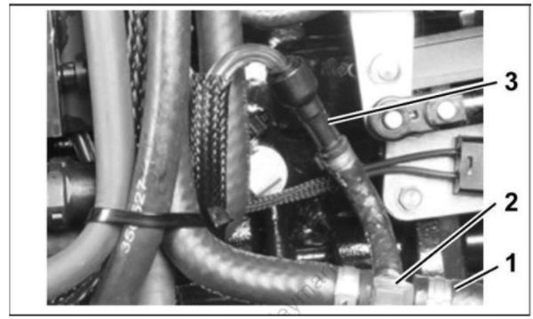
- Fuel supply hose
- In-line oil supply fitting
- Check valve
Disconnect the fuel outlet hose from the fuel filter housing.
Loosen the fuel lift pump mounting screws. Remove the fuel lift pump as an assembly.

- Screws
Installation
Fasten fuel pump to the cylinder/crankcase with pump to crankcase screws.
Apply Nut Lock to screws and install screws into crankcase. Torque screws to 24 to 36 in. lbs. (2.8 to 4.0 N·m).
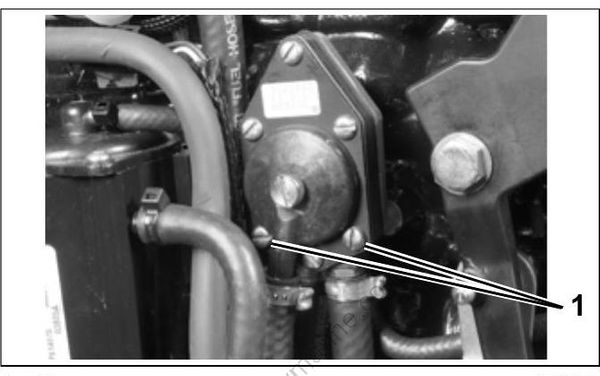
- Screws
Connect the fuel outlet hose to the fuel filter. Secure with tie strap.
Connect the fuel supply hose to the in-line oil sup ply fitting. Secure with 18.5 mm Oetiker clamp.
Route and connect the fuel lift pump pulse hose to the crankcase. Secure with tie strap.
Squeeze primer bulb to prime fuel system. Hold pressure on bulb and check for fuel leaks.
Install lower engine covers and air silencer. Connect battery cables.
Run outboard and check for fuel leaks.
Vapor Separator
Removal
Disconnect the battery cables at the battery.
Relieve fuel system pressure. Refer to Relieving Fuel System Pressure on p. 168
Disconnect circulation pump electrical connector.
Remove clamp and fuel supply manifold from top of circulation pump. Remove clamp and vapor vent hose from separator cover.
Remove clamps and vapor separator cooling water hoses.
Remove clamps and fuel return manifold and fuel supply hose from bottom of vapor separator.
Remove the vapor separator housing retainer clip.

- Retainer clip
Remove vapor separator/fuel pump from the mounting stud and slide vapor separator housing from the grooves of the isolator mounts.
Installation
Installation is essentially the reverse of removal. Pay close attention when performing the following additional tasks.
Reinstall all hoses and manifolds to original locations and secure in place with appropriate clamps. Squeeze primer bulb to prime fuel system. Hold pressure on bulb and observe for fuel leaks.
Install lower engine covers and air silencer. Connect battery cables.
Run outboard and check for fuel leaks.
Fuel Injectors
IMPORTANT: Note the proper locations and positioning of all spark plug leads and retainer clips prior to disassembly.
Remove high tension spark plug leads and retainers that are used to position the spark plug leads.
Mark fuel injector(s) to indicate cylinder location(s).
IMPORTANT: Fuel injector(s) must be installed in the correct cylinder location(s). Use the Evinrude Diagnostics Software program to confirm that the EMM programming matches injector positioning by cylinder location. The injector information screen of the diagnostic program displays injector serial numbers.
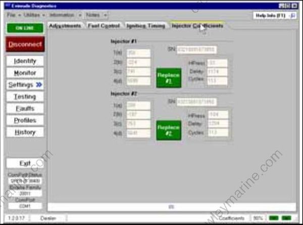
Injector Coefficients Screen
Use caution when handling fuel injectors. Prevent dirt and debris from entering fuel inlet and outlet ports of injectors or fuel tubes. Cover the injector nozzle port in cylinder head to prevent contamination of combustion chamber.
Removal
Disconnect the battery cables at the battery.
Relieve fuel system pressure. Refer to Relieving Fuel System Pressure on p. 168.
Remove oil tank assembly.
Remove the injector/fuel fitting retainer and disengage fuel manifold fittings.

- Retainers
Remove injector screws.
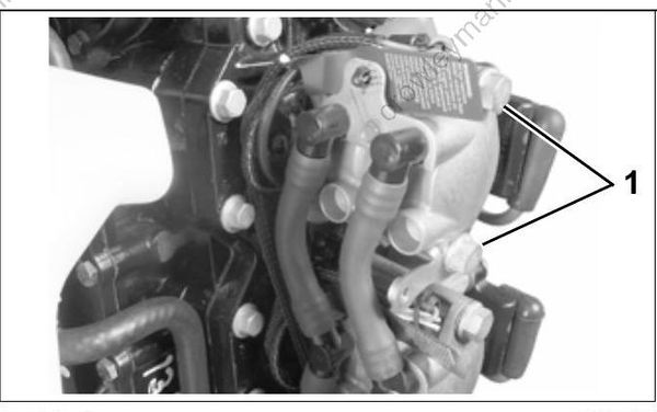
- Injector screws
Disconnect the fuel injector/coil electrical connector.
Disengage fuel manifold fittings from fuel injector and remove fuel injector and insulator.
Crush Ring Replacement
IMPORTANT: Injector crush rings must be replaced if injector is installed in a different head or cylinder location.
Use Slide Hammer assembly, P/N 391008, with Slide Hammer Adaptor kit, P/N 390898, to remove injector from mounting cup.
Thread adaptor and stud into face of injector. Hold mounting cup securely. Work slide hammer to separate injector from mount housing.
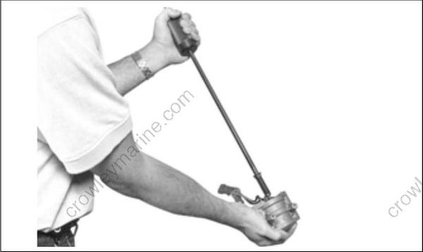
Remove adaptor from injector. Remove crush ring and O-rings from injector. Inspect and clean injector filter. Install new crush ring and O-rings. Lubricate O-rings with STP† Oil Treatment.
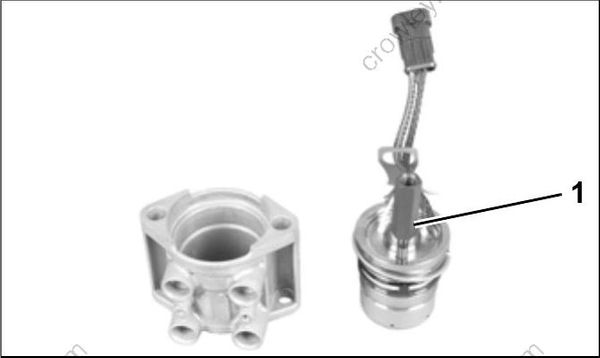
- Adaptor
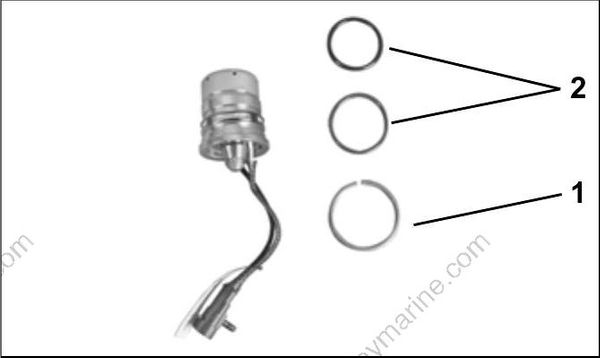
- Crush ring
- O-rings
Reinstall injector into mount housing. Press on injector face until injector seats in mount housing.

Installation
IMPORTANT: All injectors must be installed in the correct cylinder by serial number. Improper injector installation can result in outboard failure.
Installation of replacement injectors requires the use of diagnostic software and coefficient data supplied with all replacement injectors on 3.5 in. floppy disk.
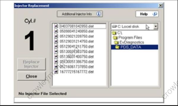
IMPORTANT: PDA software requires manually moving the coefficient data file to the “PDS_data” folder on a PC and then a “hotsync” of the PDA before the injector serial number can be reviewed on the PDA. Refer to the electronic user’s guide on the Engine Diagnostics CD.
The following items and their mating surfaces must be cleaned prior to reassembly:
- Injector
- Cylinder head
- Adapter
- Screws
- Threaded areas
All injector components must be clean to ensure correct torque tightening specifications. To prevent fuel leakage, carefully follow these installation instructions.
Position injector and insulator in the proper cylinder location.
IMPORTANT: Be careful not to pinch any wiring or hoses during assembly.
Lubricate mounting screw threads and under the head of the screw with a light coat of Triple-Guard grease. Install washers (one per screw) on injector retaining screws. Install screws and washers through mounting flange of injector and thread into cylinder head.
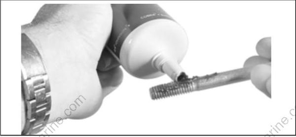
Tighten screws in stages, starting with the lower screw.
• First torque is 5 ft. lbs. (7 N·m)
• Second torque is 10 ft. lbs. (14 N·m)
• Final torque is 24 to 26 ft. lbs. (33 to 35 N·m).
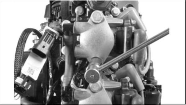
Tighten Screws in Stages
Check condition of sealing O-rings on fuel manifold fittings. Lubricate O-rings with outboard lubricant and insert fuel manifold fittings into injector. Both fittings must be fully seated into the injector fuel ports.
Install retainer and screw. Retainer must engage the outer groove of the manifold fittings.
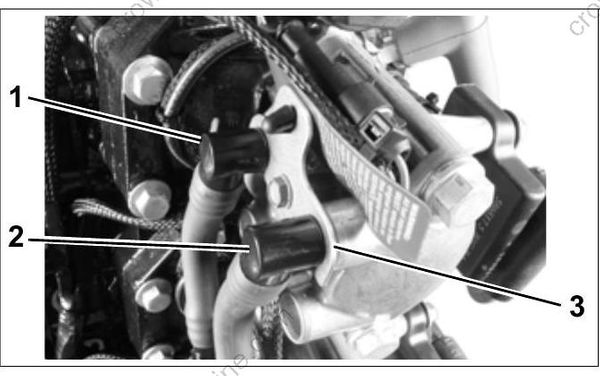
- Fuel supply manifold fitting
- Fuel return manifold fitting (White)
- Retainer
Reconnect fuel injector/coil electrical connectors and high tension spark plug leads with retainers.
Reconnect battery cables. Start outboard briefly to pressurize fuel system. Turn outboard OFF and inspect all fuel system components for leaks.
Install lower engine covers and air silencer.
IMPORTANT: : Install service injector data (3.5 in. floppy disk) by using the Injector Replacement Utility of the Evinrude Diagnostics Software program. Use the diagnostic program to confirm that all injectors are positioned properly.
Fuel Manifolds
Removal
Disconnect the battery cables at the battery.
Relieve fuel system pressure. Refer to Relieving Fuel System Pressure on p. 168.
Remove fuel manifold retainer screws and remove retainer from fuel injector.

- Screw
Disconnect fuel manifold fittings from fuel injector ports.
Remove clamps and disconnect the fuel manifolds as follows:
- Fuel supply manifold to circulation pump
- Fuel return manifold to vapor separator
Remove any tie straps used to secure manifold(s) in place, then remove the manifold assembly(s).
Installation
Installation is essentially the reverse of removal. Pay close attention when performing the following additional tasks.
Connect battery cables.
Start outboard briefly to pressurize fuel system. Turn outboard OFF and inspect all fuel system components for leaks. Repair any fuel leaks.
Install lower engine covers and air silencer.
Step 2: INTAKE MANIFOLD
Removal
Disconnect throttle linkage. Remove throttle body screws and throttle body assembly.
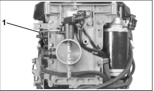
- Linkage
Remove gasket from throttle body.
Remove screws and reed plate assembly from the cylinder/crankcase assembly.
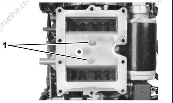
- Screws
Disassembly
Visually inspect reed valve assemblies. For disassembly of the reed valve assembly, see Inspection on p. 175.
All reed plate assembly and reed valve assemblies must be cleaned prior to reassembly. DO NOT use strong carburetor cleaner or the hot soaking tank method for cleaning.
