

COMPONENTS
The Evinrude E-TEC direct injection system consists of the following components:
- Fuel Lift Pump
- Fuel Filter
- Vapor Separator
- Fuel Circulation Pump
- Fuel Supply Manifolds
- Fuel Return Manifolds
- Fuel Injectors
Fuel Lift Pump
The fuel lift pump is a mechanical, pressure-pulse pump. The diaphragm of the pump is driven by a pulse hose that connects to the number 2 cylinder of the cylinder/crankcase assembly.

- Fuel lift pump
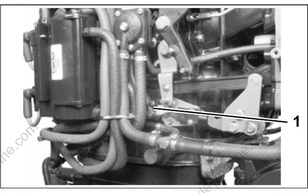
- Pulse hose
Vacuum from the fuel lift pump pulls fuel from the fuel tank. Once fuel reaches the pump, internal pump pressure forces the fuel from the pump through the fuel filter and into the vapor separator.
IMPORTANT: The oil injector supplies oil to the outboard's incoming fuel supply. A limited amount of oil is injected into the fuel supply to clean injectors and reduce internal fuel system deposits. Refer to Oil Supply and Distribution Diagram on p. 182.
Fuel Filter
The in-line filter protects the vapor separator and the high-pressure components of the fuel system from water and contaminants. Refer to INSPECTION AND MAINTENANCE SCHEDULE on p. 72 for service frequency.

- Filter
Vapor Separator
The vapor separator:
- Serves as a water-cooled fuel reservoir to accumulate incoming fuel from the fuel lift pump and from the fuel return manifold;
- Contains a float controlling the venting of fuel vapors; and
- Contains a fuel pressure regulator for the high pressure fuel system.
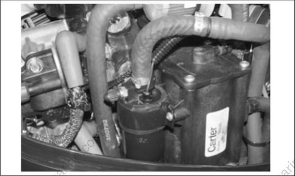
The vapor separator is serviced as an assembly and includes the fuel circulation pump.

Vapor Separator Assembly
- Circulation pump
Fuel Reservoir
The vapor separator accumulates fuel in an internal fuel reservoir and supplies fuel to the electric circulation pump. It is water-cooled to enhance vapor separating capabilities.
Cooling
Water is used to cool the fuel as it flows through the vapor separator. The water cavity of the separator self-drains when the outboard is stored vertically. Refer to HOSE ROUTING AND WATER FLOW DIAGRAM on p. 192.
Venting
The fuel vapor vent regulates fuel vapor pressure in the fuel system.

- Vent
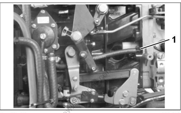
- Vent hose
The vapor separator vent is opened and closed by a float valve. The float valve moves relative to the fuel level in the fuel chamber. Hot fuel causes an increase in vapor pressure. This results in a lower fuel level in the vapor separator. The float valve drops and the vent opens. This allows fuel vapor to flow to the intake manifold through the vent hose.
As the vapor pressure in the vapor separator decreases, the fuel level begins to increase. An increase in the fuel level raises the float valve and the vent closes.
Pressure Regulator
The fuel pressure regulator helps maintain consistent fuel pressure in the fuel system.
Fuel returning from the injectors enters the fuel chamber of the vapor separator through a pressure regulator. The pressure regulator maintains approximately 20 to 30 psi (138 to 207 kPa) of fuel pressure in the high pressure side of the fuel system.
Fuel Circulation Pump
The fuel circulation pump is an electric high pressure fuel pump. The pump is controlled by the EMM.
Fuel Supply
The pump is mounted to the vapor separator and draws fuel from the fuel chamber. The fuel injectors receive pressurized fuel from a fuel supply manifold connected directly to the circulation pump.
Electrical Circuit
Activation of the circulation pump is controlled by the EMM. The outboard must be cranking or running for the circulation pump to be activated. Activation of the circulation pump requires CPS input to the EMM.
Fuel Manifolds
The fuel supply and return manifolds route fuel through the high pressure side of the fuel system.
Fuel Supply Manifold
The fuel supply manifold supplies pressurized fuel to the inlet port of each fuel injector.
Fuel Return Manifold
The fuel return manifold provides a route for fuel passing through the fuel injectors to flow back to the fuel chamber of the vapor separator.
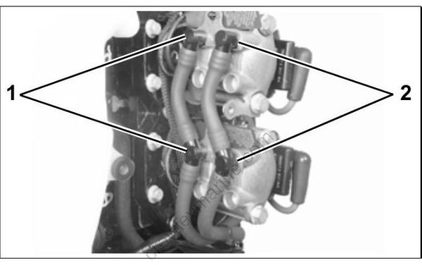
- Inlet port(s)
- Fuel return manifold
Fuel Injectors
Fuel injectors are fuel metering (55 V), electric injector pumps bolted directly to the cylinder head. The EMM supplies 55 V and controls the activation of each injector
Fuel Flow Compensation
Flow tests included in the injector manufacturing process measure the flow rates of each injector. Each injector's fuel flow rate is recorded and converted to specific coefficients. These coefficients are assigned to the injector by serial number.
Each individual service injector includes these coefficients on a 3.5 in. floppy disk. The disk also includes the software necessary to install a replacement injector. This software enables the EMM to control each injector based on unique fuel flow characteristics.
IMPORTANT: The cylinder location of each injector must always be maintained. EMM programming is associated with the cylinder location of each injector.
Injector Fuel Supply
Fuel is supplied to the injectors by the fuel circulation pump and the fuel supply manifold.
Each injector has internal fuel passages. These passages are designed to:
- Provide fuel to the injector's injection chamber; and
- Route fuel through the injector housing to cool the injector coil and armature.

