

Block Venting
A fitting and hose connected to the top of the exhaust cover allows the constant movement of water and/or air from the block. Circulated water flows through the EMM and vapor separator before exiting through the overboard indicator.
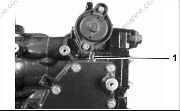
- Fitting
Water Pressure Connection
Fitting and hose for accessory water pressure gauge is connected at top of cylinder block adjacent to the pressure relief valve housing.
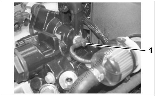
1.Fitting
| Model | Water Pressure @ 5000 RPM (Minimum) |
|---|---|
| 40 – 60 HP | 11 psi |
OPERATION
Cylinder Block / Cylinder Head Cooling
The thermostat is located in the top of the cylinder head. A separate pressure relief valve is positioned in the top of the cylinder block adjacent to the exhaust cover. The thermostat and pressure relief valve control the flow of water entering the vertical water passages of the cylinder head.
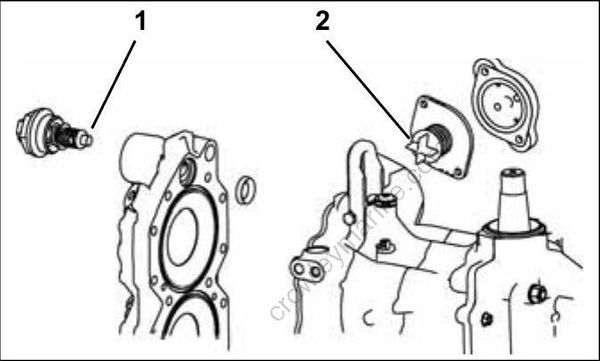
- Thermostat
- Pressure relief valve
The controlled discharge of water from the thermostat and/or the pressure relief valve allows water from the top of the cylinder block to enter the cylinder head. Water flows down through the cylinder head and exits at the bottom of the cylinder head. The water outlet of cylinder head aligns with a water passage at the bottom of the cylinder block. Circulated water flows through the outlet passage of the block to the exhaust housing and then out of the outboard.
At low speed, temperature is thermostatically controlled. The spring loaded thermostat remains on a seat in the cylinder head. Water flows through the thermostat only when it is open. The thermostat opens at approximately 143°F (60°C).
At higher speeds, temperature is water pressure controlled. The pressure relief valve spring tension provides the proper “blow off” pressure. The valve lifts from the seat in the cylinder head at approximately 1800 RPM. Cooling water flows around the valve to achieve high speed cooling.
EMM and Vapor Separator Cooling
Cooling water is routed through the EMM water cavity. Cooling of the EMM minimizes the temperatures of internal components.
Cooling water is routed to the water inlet fitting of the vapor separator water cavity. Cooling the vapor separator fuel chamber minimizes fuel vaporization.
Cooling water from the EMM and vapor separator exits through the overboard indicator. See HOSE ROUTING AND WATER FLOW DIAGRAM on p. 192.
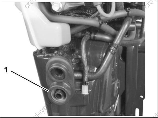
- Overboard indicator
IMPORTANT: Improper EMM cooling will activate service codes (code 29 and 25) and initiate
S.A.F.E. or SHUTDOWN. Refer to EMM DIAGNOSTICS on p. 93 for specific service code information
THERMOSTAT SERVICING
Disassembly
Remove the thermostat cover and O-ring from cylinder head.
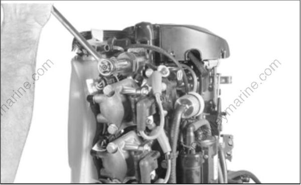
Remove spring, thermostat, and gasket.
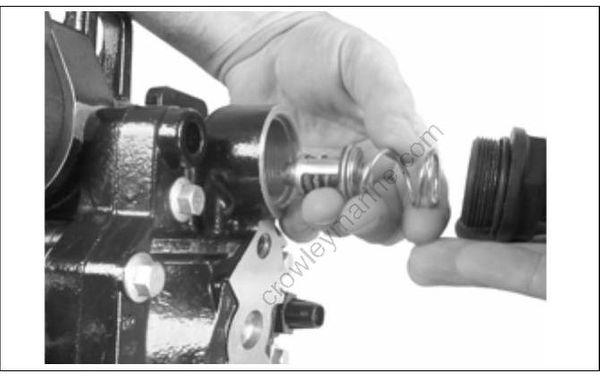
Remove the cylinder head if cylinder head seal requires replacement. Place new seal in the cylinder.
