REMOVAL
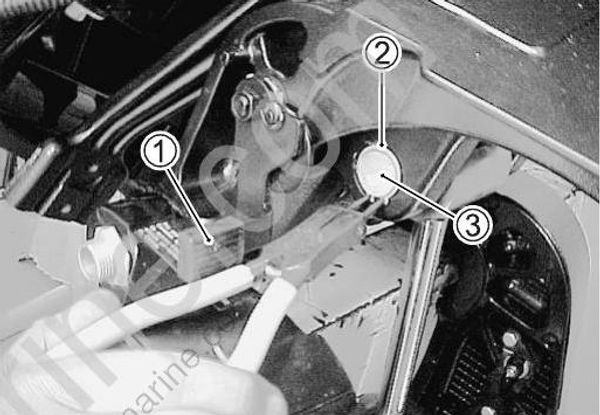
- Raise the engine to the full tilt position and the lower manual tilt lock levers (1).
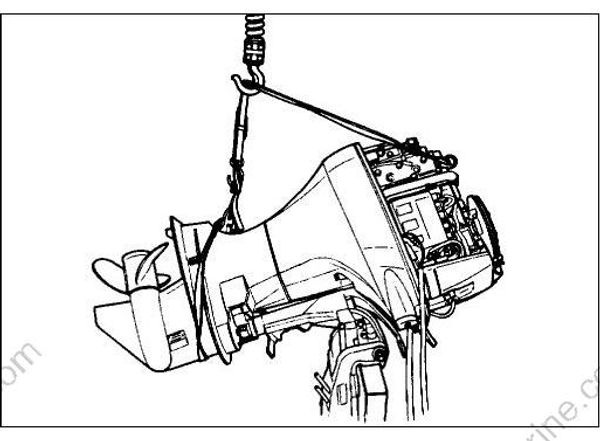
During the following procedures, the engine must be firmly secured and its weight fully supported. (See right)
- Remove the tilt rod snap ring (2) and push the tilt cylinder upper shaft pin (3) out.
- Lower the tilt rod to the full down position and disconnect the battery cable.
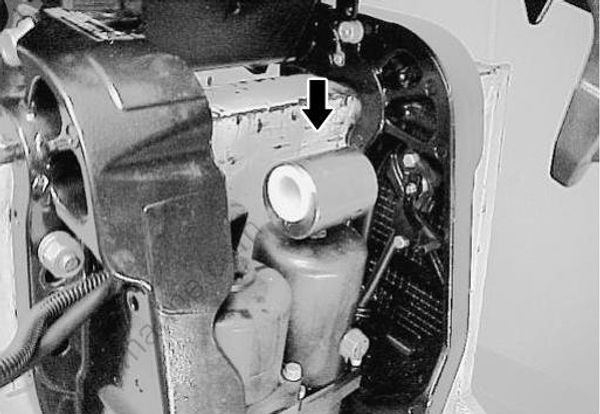
- Remove the silencer cover bolt and the fastening band.
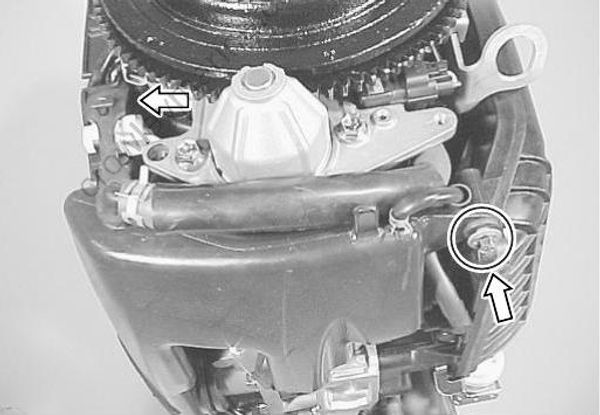
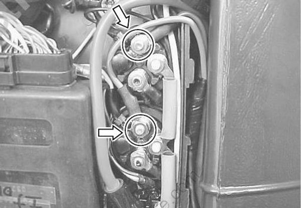
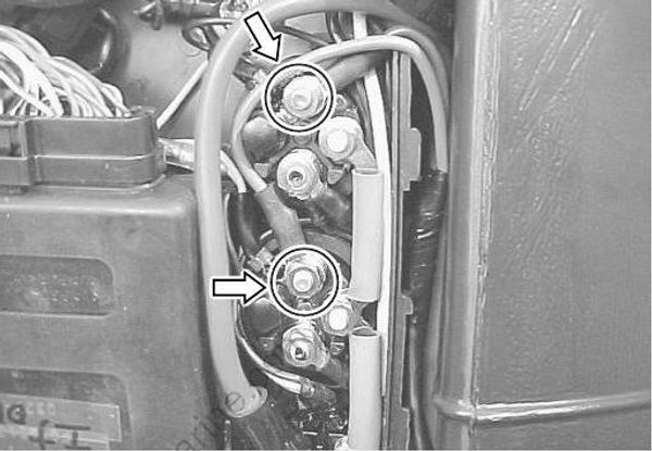
Disconnect the PTT motor cable wire leads (Green, Blue) from the PTT motor relays.
Remove the PTT motor cable from the engine lower cover.
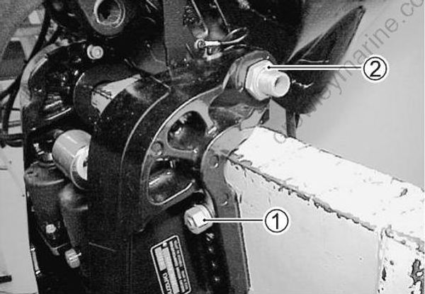
- Remove the starboard motor mounting bolts (1) and the clamp bracket shaft nut (2).
Remove the PTT cylinder lower shaft bolts (1).
Remove the two bolts and the anode (2).
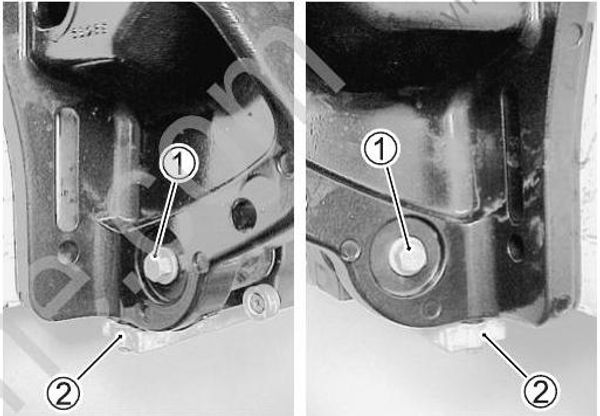
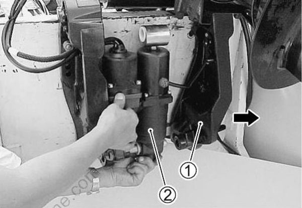
- Slide the starboard clamp bracket (1) off the clamp bracket shaft, then remove the PTT unit (2).
DISASSEMBLY
Before disassembly, wash the PTT body with a stiff bristle brush and hot, soapy water to remove sand or dirt and dry the PTT body with compressed air.
- Place the lower mounting eye of the PTT cylinder in a vise. Tighten the vise only enough to secure the PTT unit, do not over tighten.
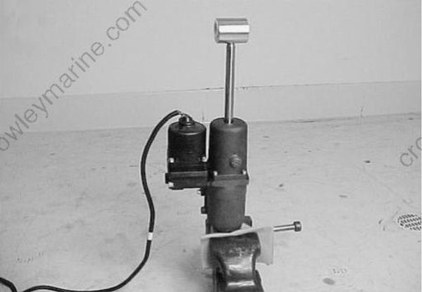
To prevent damage to the PTT cylinder use wood blocks, vise jaw protectors, etc., between the vise jaws and the PTT components before tightening the vise.
Connect the PTT motor cable leads (Green, Blue) to the battery and operate the PTT motor until the tilt piston rod is at a maximum stroke. (full-tilt up position)
Remove the PTT motor. (See the page 8-10.)
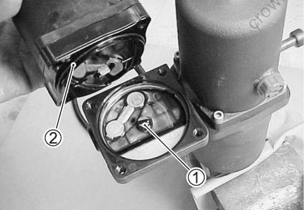
Note the position of the drive joint (1) and the O-ring (2), before removing them.
Remove the fill plug and drain the PTT oil into a suitable container.
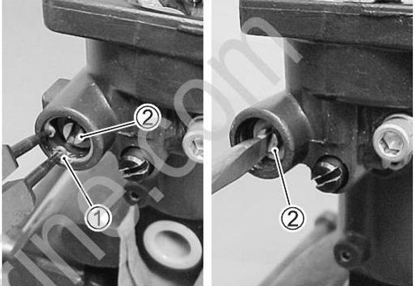
Remove the manual release valve snap ring (1), then remove the manual release valve (2).
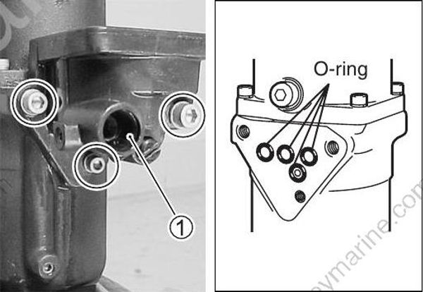
- Remove the three bolts securing the PTT pump case (1), then detach the PTT pump case from the PTT body. Note the position of the O-rings and remove them.
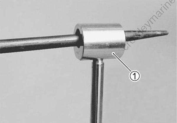
- Remove the upper eye (1).
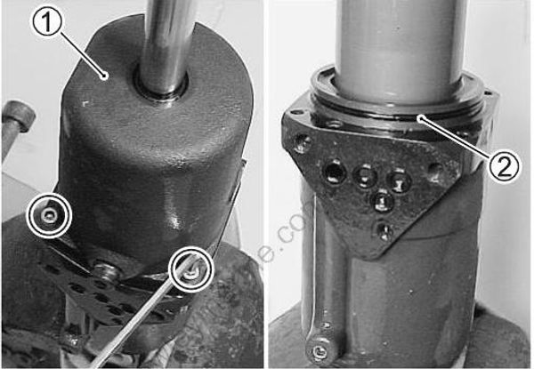
Remove the four bolts securing the cylinder cover (1), then detach the cover from the PTT body.
Remove the O-ring (2).
INSPECTION
Arrange all components on a clean sheet of paper.
Do not lay the PTT components out on a rag, as dirt or lint may be transferred to these items which may cause possible system operating problems.
If excessive wear, cracks, defective or other damage is found on any component, replace component.
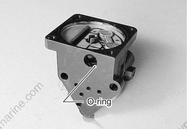
● Inspect the PTT pump case for cracks, nicks, stripped threads and any other imperfections.
Replace if necessary.
● Inspect the cylinder cover for cracks, nicks or damage. Replace if necessary.
● Inspect the cylinder cover seal for cuts, nicks or wear.
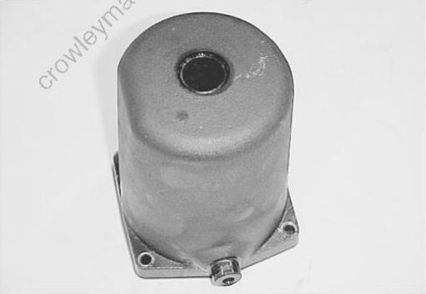
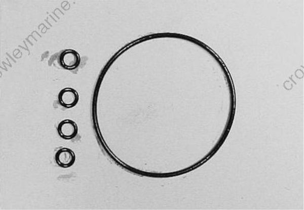
● Inspect the O-rings for cuts, nicks or tears.
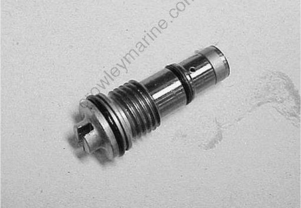
● Inspect the manual release valve for damage. Replace if necessary.
● Inspect the O-rings for cuts, nicks or tears.
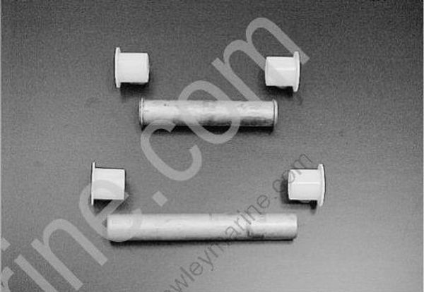
● Inspect the lower shaft and the upper shaft for bent, twist or other damage.
Replace if necessary.
● Inspect all bushings for excessive wear or other damage. Replace if necessary.
If bushing fit is loose when installing, replace the bushing.
REASSEMBLY
Assembly is reverse order of disassembly with the special attention to the following steps.
● Do not re-use the O-ring and seal once removed. Always use new parts.
● Lubricate all components and O-rings with the PTT fluid before assembly.
● Do not re-use the PTT fluid. Always refill with new fluid.
TILT CYLINDER COVER
Apply the PTT fluid to the cylinder cover seal, then install the cylinder cover.
Tighten the four bolts securely.
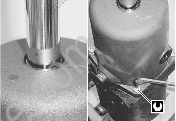
Cylinder cover bolt: 4.7 N●m (0.47 kg●m, 3.4 lb●ft)
UPPER EYE
Apply the Thread Lock to the threads of the upper eye before threading it onto the tilt rod.
Tighten the upper eye to the specified torque.
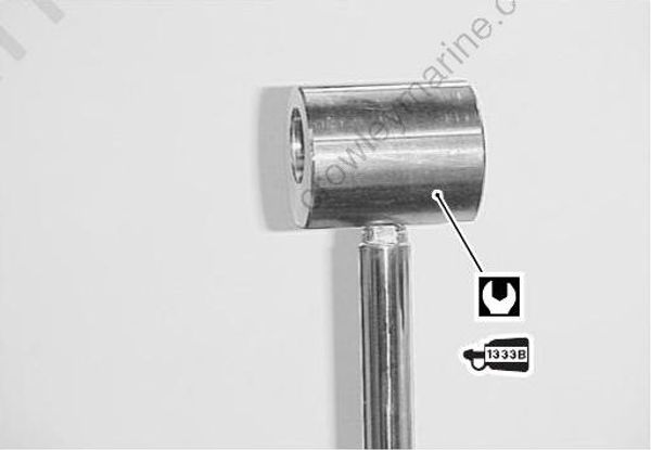
Upper eye: 108 N●m (10.8 kg●m, 78.0 lb●ft)
99000-32020: THREAD LOCK SUPER “1333B”
PTT PUMP CASE
- Install the four O-rings to the PTT body.
Lubricate the O-ring with the PTT fluid before installing the PTT body.
- Install the PTT pump case, then tighten the three bolts to the specified torque.
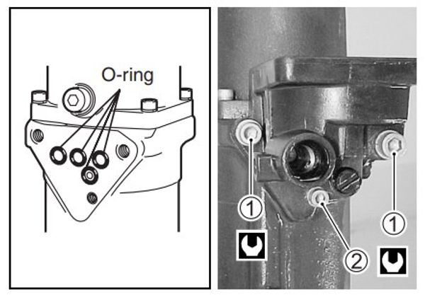
PTT pump case bolt:
(1) 8 N●m (0.8 kg●m, 5.8 lb●ft)
(2) 5.5 N●m (0.55 kg●m, 4.0 lb●ft)
MANUAL RELEASE VALVE
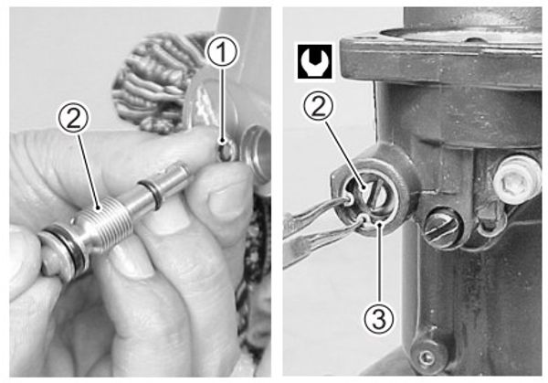
Oil and install the seal washer (1) and the manual release valve (2).
Tighten the valve to the specified torque.
Manual release valve: 3.6 N●m (0.36 kg●m, 2.6 lb●ft)
- Install snap ring (3).
PTT MOTOR
See the PTT MOTOR INSTALLATION section on the page 8-14.
AIR BLEEDING
● Pour the recommended PTT fluid in to the reservoir until the specified level.
● Perform the air bleeding procedure.
See the AIR BLEEDING section on the page 8-3.
PTT MOTOR
PTT MOTOR REMOVAL
Before removing the PTT motor, wash the PTT body with a stiff bristle brush and hot, soapy water to remove sand or dirt and dry the PTT body with compressed air.
- Place the lower mounting eye of the PTT cylinder in a vise. Tighten the vise only enough to secure the PTT unit, do not over tighten.
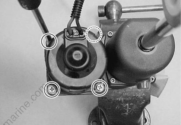
To prevent damage to the PTT cylinder use wood blocks, vise jaw protectors, etc., between the vise jaws and the PTT components before tightening the vise.
- Remove the four bolts securing the PTT motor to the PTT pump case.
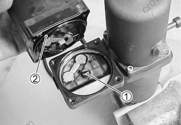
- Detach the PTT motor from the PTT pump case.
Note the position of the drive joint (1) and the O-ring (2) and remove them.
PTT MOTOR DISASSEMBLY
For correct assembly, scribe an alignment mark on the field case and the brush holder.
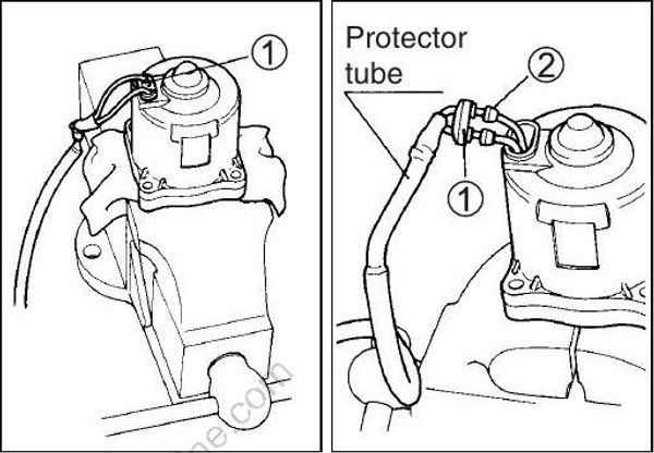
Remove the tape from the PTT motor cables and the cable protector tube, then slide the cable protector tube upward.
Remove the screw securing the motor cable holder (1), then slide the motor cable holder and the grommets (2) out as shown.
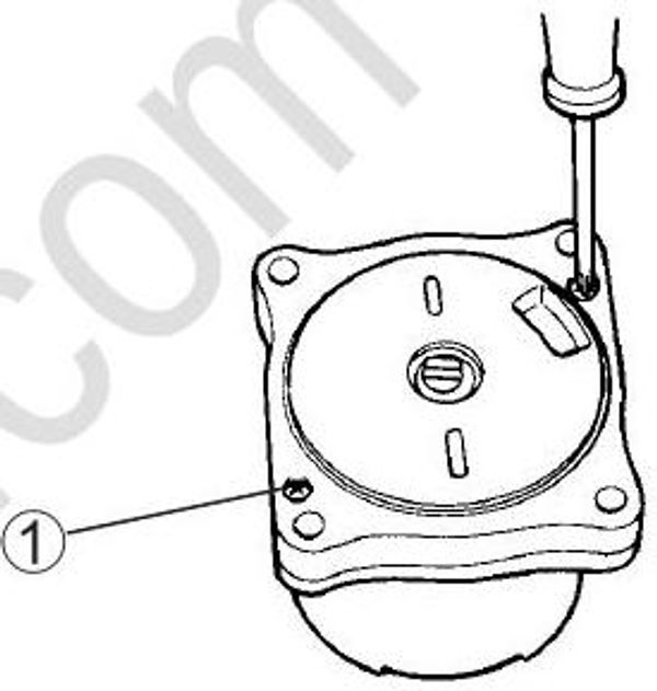
- Remove the two screws (1) securing the field case to the brush holder.
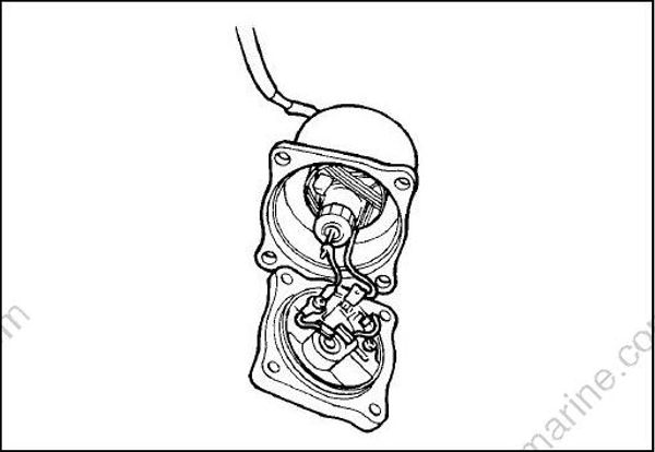
- Slide the field case upward and away from the brush holder.
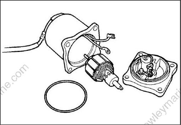
When separating the field case from the brush holder, proceed by pushing the PTT motor cables into the brush holder side.
Disconnect the PTT motor cables from the brush holder.
Remove the armature from the field case.
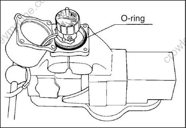
Note the position of the O-ring encircling the brush holder.
PTT MOTOR INSPECTION
Armature and Commutator
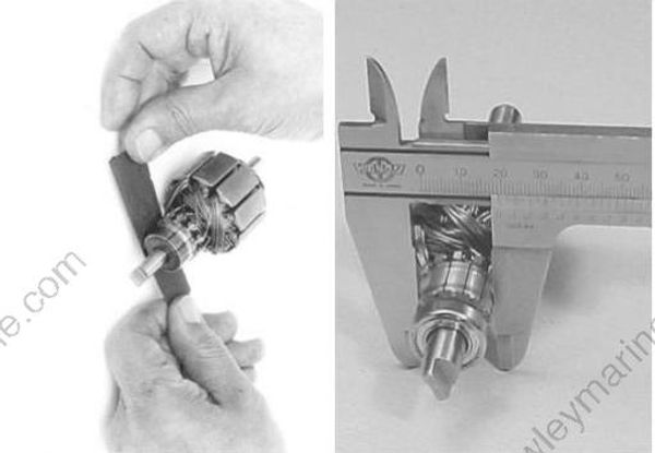
- Inspect the commutator surface for gum or dirt. Clean with #500 grit emery paper if necessary.
Measure the commutator outside diameter.
09900-20101: Vernier calipers
Commutator outside diameter:
Standard: 22.0 mm (0.87 in)
Service limit: 21.0 mm (0.83 in)
If the measurement exceeds the service limit, replace the armature.
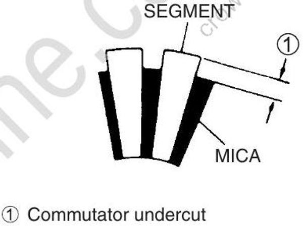
- Measure the commutator undercut (depth) between the mica (insulator) and the segments.
Commutator undercut (1) (depth):
Standard: 1.6 – 1.9 mm (0.06 – 0.07 in)
Service limit: 1.3 mm (0.05 in)
If the measurement exceeds the service limit, cut the mica to the specified depth.
Remove all particles of the mica and the metal using compressed air.
Wear safety grasses when using compressed air.
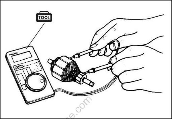
- Inspect the continuity between the commutator and the armature core/shaft.
If the continuity exists, replace the armature.
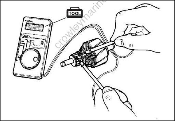
09930-99320: Digital tester
Tester range: → ← (Continuity)
- Inspect the continuity between the adjacent commutator segments.
If no continuity exists, replace the armature.
Brushes
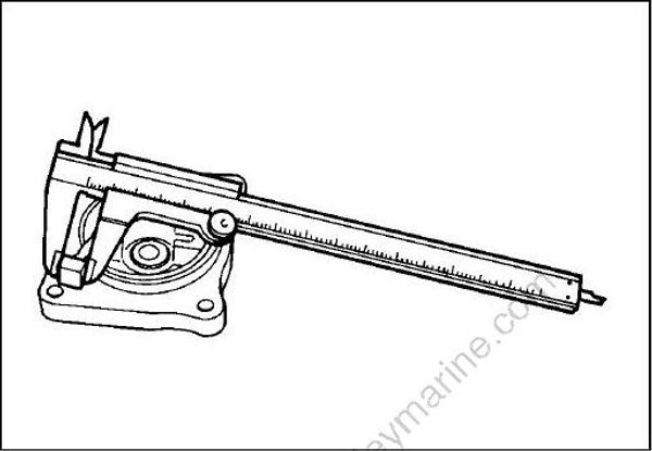
Measure the length of each brush.
09900-20101: Vernier calipers
Brush length:
Standard: 9.8 mm (0.39 in)
Service limit: 5.5 mm (0.22 in)
If the measurement exceeds the service limit, replaced the brush.
O-Ring
Inspect the O-ring between the PTT motor and the PTT pump case for cuts, nicks or tears.
PTT MOTOR REASSEMBLY
Reassembly is reverse order of disassembly with the special attention to the following steps.
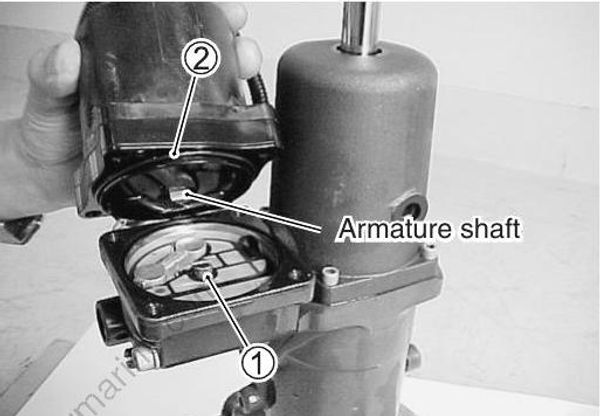
- Install the armature to the brush holder first.
When installing the armature, exercise care to avoid breaking the brushes.
Match up previously scribed alignment marks.
When assembling the field case to the brush holder, proceed by pulling the PTT motor cables out of the field case.
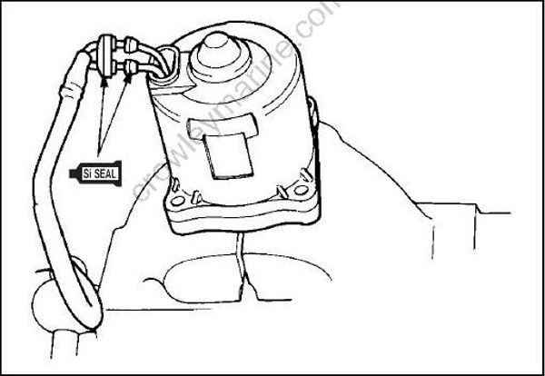
Apply the Silicone Seal to the PTT motor cable holder and the grommets, then install the cable holder screw.
99000-31120: SUZUKI SILICONE SEAL
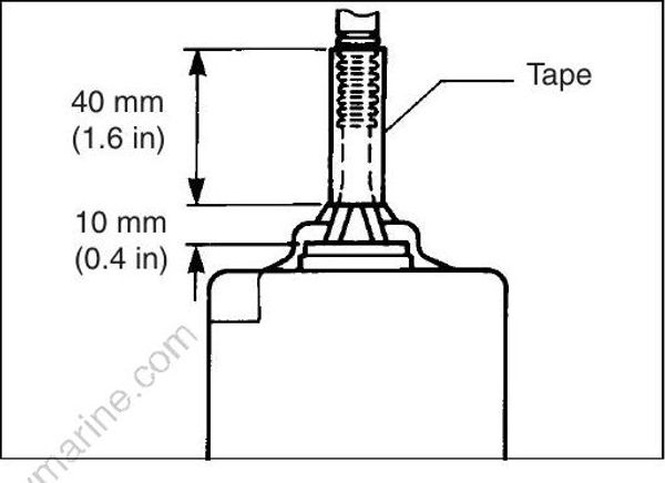
- Fix the cable protector tube to the PTT motor cables with heat-resisting tape.
PTT MOTOR INSTALLATION
Installation is reverse order of removal with the special attention to the following steps.
Ensure that the drive joint (1) is aligned and firmly inserted into the gear pump assembly.
Fit the O-ring (2) to the PTT motor.
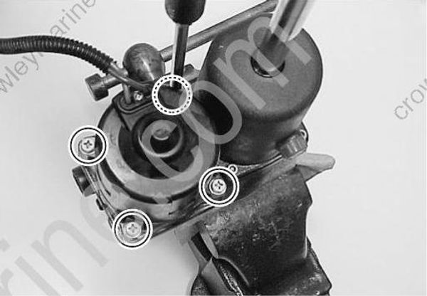
Check the level of the PTT fluid contained in the PTT pump case. If the level is low, add the recommended PTT fluid until the level with the mating surface of the PTT motor.
Ensure that the faces of the PTT motor and the pump unit are free of dirt or debris.
When attaching the PTT motor to the PTT pump case, ensure that the tip of the armature shaft fits firmly into the drive joint (1).
- Tighten the four bolts to the specified torque.
PTT motor screw: 5 N•m (0.5 kg•m, 3.6 lb•ft)
Pour the recommended PTT fluid into the reservoir until the specified level.
Perform the air bleeding procedure.
See the AIR BLEEDING section on the page 8-3.
INSTALLATION
Installation is reverse order of removal with the special attention to the following steps.
Lower the tilt rod to the full down position.
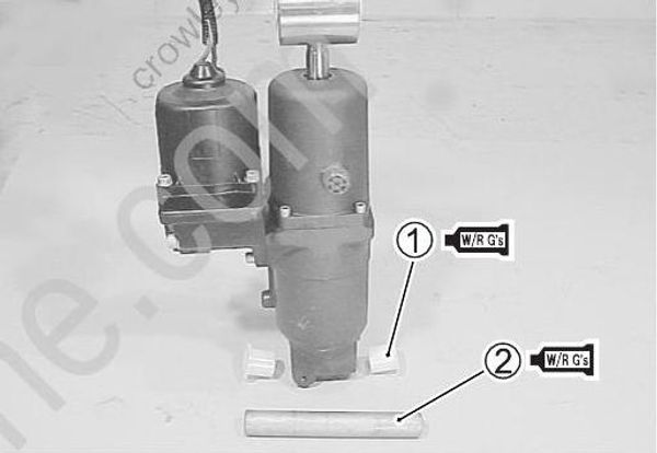
Apply the Water Resistant Grease to the tilt cylinder lower shaft and the lower shaft bushing.
Install the bushings (1) and the cylinder lower shaft (2) to the PTT unit.
99000-25161: SUZUKI WATER RESISTANT GREASE
Place the PTT unit in position, then install the clamp bracket.
Tighten the clamp bracket shaft nut to the specified torque.

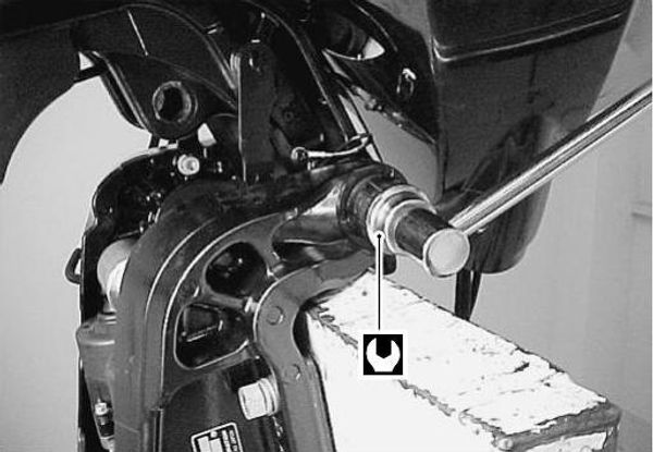
Clamp bracket shaft nut: 43 N•m (4.3 kg•m, 31.0 lb•ft)
- Tighten the lower shaft bolts (1), pre-coated with the thread lock, to the specified torque.
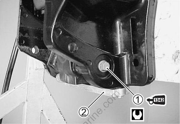
99000-32050: THREAD LOCK “1342”
Cylinder lower shaft bolt: 50 N●m (5.0 kg●m, 36.0 lb●ft)
Install the anode (2), then tighten the bolts securely.
Apply the Water Resistant Grease to the tilt rod upper bushings (1), then install the bushings in the tilt rod.
Operate the PTT motor to extend the PTT rod upward. Align the tilt rod with the hole in the swivel bracket as the tilt rod extends.
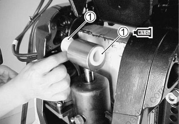
99000-25161: SUZUKI WATER RESISTANT GREASE
- Apply the Water Resistant Grease to the PTT rod upper shaft (1), then insert the shaft through the swivel bracket and the tilt rod.
99000-25161: SUZUKI WATER RESISTANT GREASE
- Secure the upper shaft with the snap ring (2).
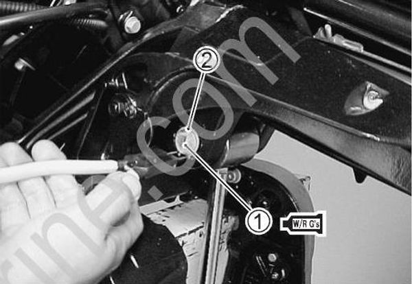
- Route the PTT motor cable in through the lower cover and connect the terminals to the PTT motor relays.
(Cable routing – See the WIRE/HOSE ROUTING section.)