

OPERATION
The power trim and tilt system is operated by a “rocker” type switch (protected by a rubber thumb pad) on top of the remote control box handle.
When the switch is depressed, power is delivered to the electric motor via the relevant relay. The relay with the Blue wire connected to the PTT pump is for trim/tilt “UP”, while the relay with the Green wire is for trim/tilt “DOWN”.
COMPONENTS

(1) Gear pump
(2) “UP” pressure main check valve
(3) “UP” relief valve
(4) “DOWN” relief valve
(5) Spool valve (B)
(6) Check valve (B)
(7) Check valve (A)
(8) Spool valve (A)
(9) “DOWN” pressure main check valve
PRINCIPLES OF OPERATION
TRIM/TILT “UP”CIRCUIT
When the PTT switch is operated “UP” position, the electric motor and gear pump (4) will operation on clockwise direction.
Pressurized oil will open check valve (A), oil will flow from reservoir to spool valve (A) via pump and spool valve (B).
The spool valve (A) will down, then “DOWN” pressure main check valve (1) will open.
Oil in the upper chamber will return to pump via 2-way valve, and then oil pressure will rise and open “UP” pressure main check valve (2), then oil will flow to lower cylinder chamber of cylinder.
It makes the piston rod push up and the engine tilt up.
To keep oil level, oil flows from reservoir to pump through the check valve (A).
Oil through the “DOWN” pressure main check valve (1) and returns to pump.
When trim motor stops, both the “DOWN” pressure main check valve (1) and the “UP” pressure main check valve (2) will close to retain tilt/trim position.
In the trim area, trim piston and floating tube are moving with piston rod.
When full trim/tilt “UP” position is attained, sustained operation of the “UP” relay will have no effect, as pump oil flow will be returned to the reservoir through the “UP” relief valve (3).
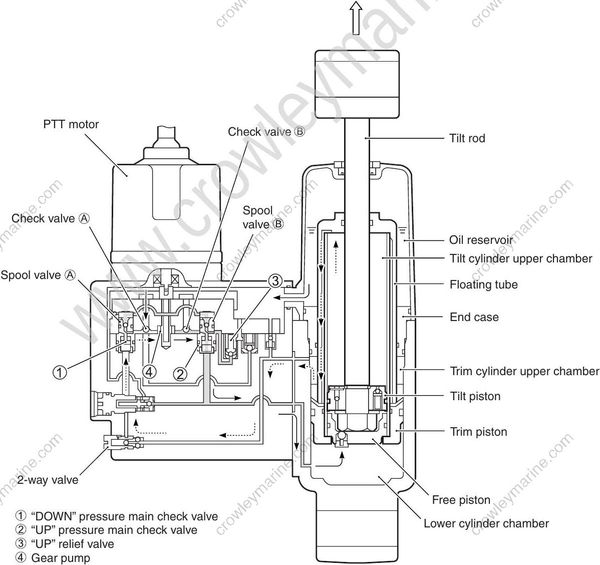
(1) “DOWN” pressure main check valve
(2) “UP” pressure main check valve
(3) “UP” relief valve
(4) Gear pump
TRIM/TILT “DOWN” CIRCUIT
When the PTT switch is operated “DOWN” position, the electric motor and gear pump will operation on counterclockwise direction.
Check valve (B) will open; oil will flow from reservoir to spool valve (A).
It makes spool valve (B) move to downward, then “UP” pressure main check valve (2) open.
Oil in the lower chamber will return to pump, and then oil pressure will rise and open “DOWN” pressure main check valve (1), then oil will flow to upper cylinder chamber of cylinder.
It makes the piston rod push down and the engine will tilt down.
To keep oil level, oil flows from reservoir to pump through the check valve (B).
Surplus oil in the pump through the “DOWN” relief valve (3) and returns to reservoir.
When trim motor stops, both the “DOWN” pressure main check valve (1) and the “UP” pressure main check valve (2) will close to retain tilt/trim position.
In the trim area, trim piston and floating tube are moving with piston rod.
When full trim/tilt “DOWN” position is attained, sustained operation of the “DOWN” relay will have no effect, as pump oil flow will be returned to the reservoir through the “DOWN” relief valve (3).

(1) “DOWN” pressure main check valve
(2) “UP” pressure main check valve
(3) “DOWN” relief valve
(4) Gear pump
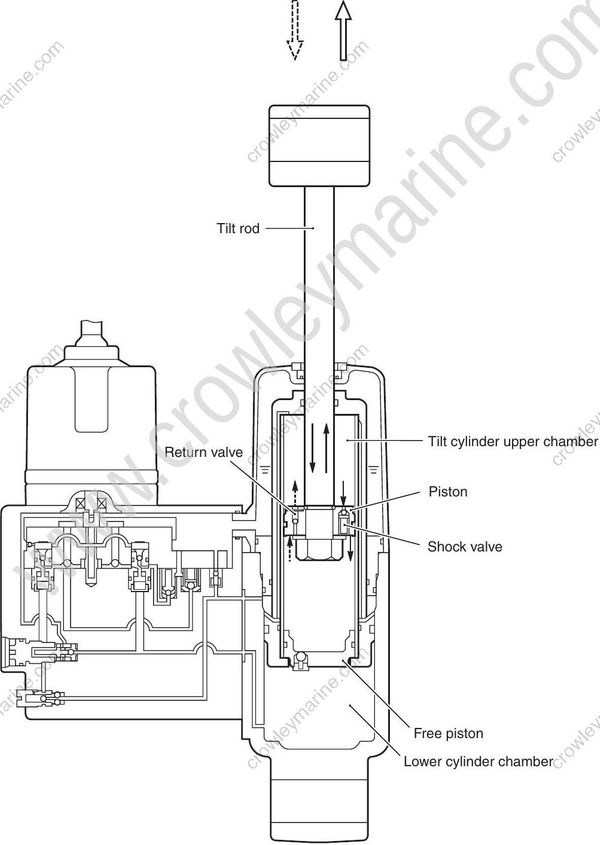
SHOCK ABSORBER CIRCUIT
(i) Shock valve
Should the lower unit strike an underwater object whilst in motion, the piston will rise abruptly, creating a sudden high impact pressure in the upper cylinder chamber. The shock valve will then open, allowing oil to flow into the area between the tilt ram piston and the free piston, thereby dampening (absorbing) the impact.
(ii) Return valve
When the point of impact has passed, propeller thrust and motor weight will force the tilt ram piston back downwards. The oil from between the ram piston and the free piston is then expelled through the return valve before flowing into the upper cylinder chamber.
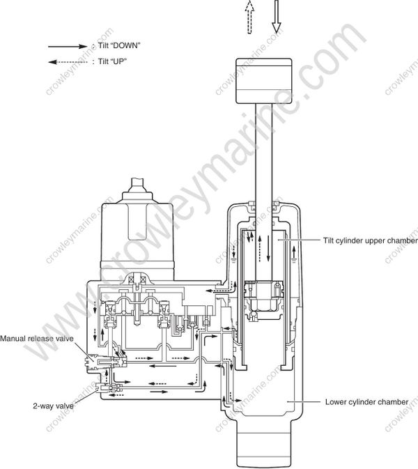
MANUAL RELEASE CIRCUIT (MANUAL VALVE)
Operation: Turn manual valve maximum three (3) full turns counterclockwise.
When the manual valve is loosened, oil will flow unimpeded (without resistance) through the internal pump tubes, thereby facilitating manual tilting or lowering of the outboard. To hold the engine in a selected position, the manual valve must be closed again.
THERMAL VALVE
As temperature goes up, oil pressure will increase and the oil in PTT unit will expand.
High oil pressure in the upper cylinder chamber caused by rising of outside temperature will release thermal valve and make the oil flow to reservoir to prevent from damaging of PTT unit.

