

REMOVAL
Before removing electric parts holder:
- Disconnect battery cables from battery.
Remove the electric parts holder cover with pushing it upward.
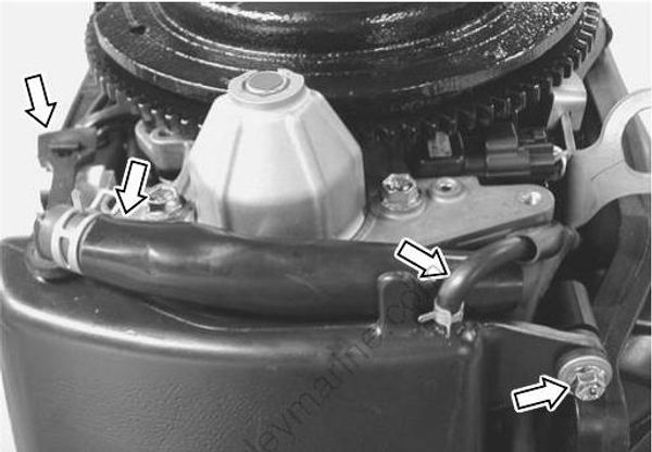
Remove the breather hose and evaporation hose.
Remove the bolt, the fastening band and the silencer cover.
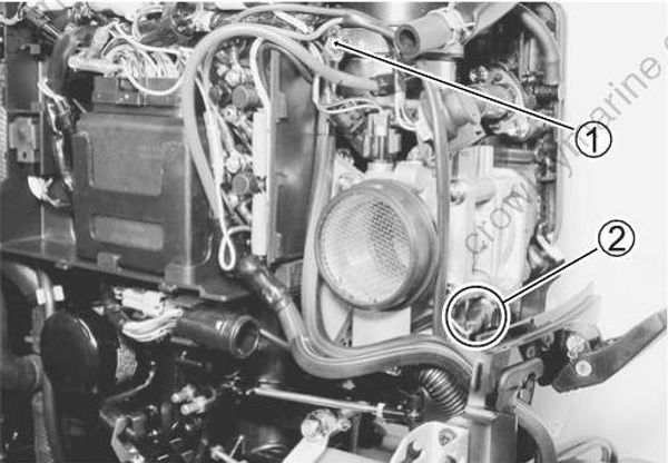
Remove the bolt (1) and disconnect the wires.
Disconnect the CTP switch wire (2).
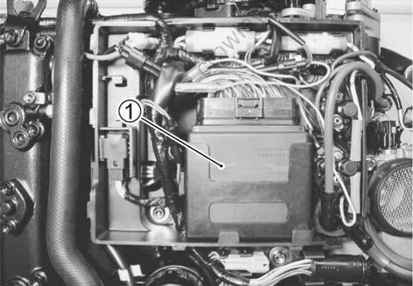
Remove the ECM (1).
Disconnect the following wires in the electric parts holder.
Connector of cylinder temp. sensor (Lg/W, B/W)
Connector of ex. manifold temp. sensor (V/W, B/W)
Blue wire on oil pressure switch
Connector of PTT motor relay (P)
Connector of PTT motor relay (Lbl)
Connector of battery charge coil (Y, Y, Y)
Connector of rectifier & regulator (W)
All cables/wires on starter motor relay terminals
Connector of starter motor relay (Y/G)
Blue wire on PTT motor relay terminal
Green wire on PTT motor relay terminal
Connector of neutral switch (Y/G, Br)
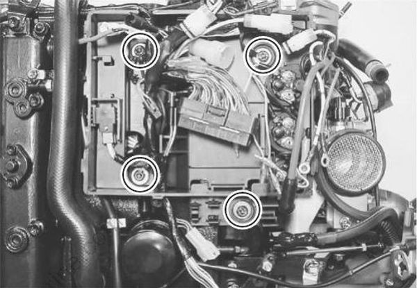
- Remove the four bolts and the electric parts holder.
INSTALLATION
Installation is reverse order of removal.
See the page 10-2 to 10-5 for check of wire routing.
