DIGITAL GAUGE
The digital gauge and the components required for installing the digital gauge are available as optional com ponents.
The new gauge system components are as follows.
| Refer No. | Part name | Part No. | Remarks |
|---|---|---|---|
| - | Speedometer assy. [NOTE 2] | 34100-98J00 | Max. 130 KM/H (Black) |
| - | Speedometer assy. [NOTE 2] | 34100-98J10 | Max. 130 KM/H (White) |
| - | Speedometer assy. [NOTE 2] | 34100-98J20 | Max. 80 KM/H (Black) |
| - | Speedometer assy. [NOTE 2] | 34100-98J30 | Max. 80 KM/H (White) |
| - | Tachometer assy. [NOTE 1] | 34200-98J01 | Black |
| - | Tachometer assy. [NOTE 1] | 34200-98J11 | White |
| - | Fuel gauge assy. | 34300-98J00 | Black |
| - | Fuel gauge assy | 34300-98J10 | White |
| - | Voltage meter assy. | 34600-98J00 | Black |
| - | Voltage meter assy. | 34600-98J10 | White |
| - | Trim meter assy. | 34800-98J00 | Black |
| - | Trim meter assy. | 34800-98J10 | White |
| - | Active hub | 34921-98J00 | |
| - | Passive hub | 34921-98J10 | Multiple engine |
| - | Interface module [NOTE 1] | 34922-98J01 | |
| (1) | Adaptor, Interface module harness | 36661-93J00 | |
| (2) | Interface harness assy | 36661-98J00 | |
| - | Hub harness (1 M) | 36662-98J00 | Dual stations |
| - | Hub harness (6.5 M) | 36662-98J10 | Dual stations |
| (3) | Active hub power harness (2.5 M) | 36663-98J00 | |
| (3) | Active hub power harness (6 M) | 36663-98J10 | |
| (4) | 3” gauge harness assy | 36664-98J00 | |
| (5) | 2” gauge harness assy. | 36664-98J10 | |
| (6) | Jumper wire | 36665-98J00 | |
| - | 8 pin connector cap | 36666-98J00 | In case of one piece of 3 inch gauge |
| (7) | 6 pin connector cap | 36666-98J10 | |
| - | 2 pin connector cap | 36667-98J00 | Dual stations |
• Tachometer (P/no. 34200-98J00, 34200-98J10) and interface module (P/no. 34922-98J00) for DF300 can not be used.
• Conversely, New tachometer (P/no. 34200-98J01, 34200-98J11) and interface module (P/no. 34922-98J01) can be used for DF300.
• Requires commercially available NMEA 2000 transducer with speed input.
MODIFICATION OF HARNESS CONNECTION
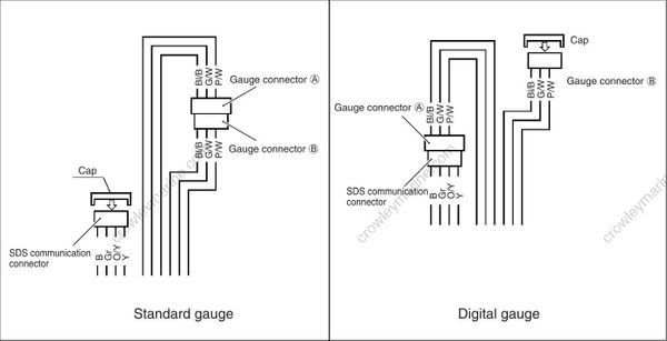
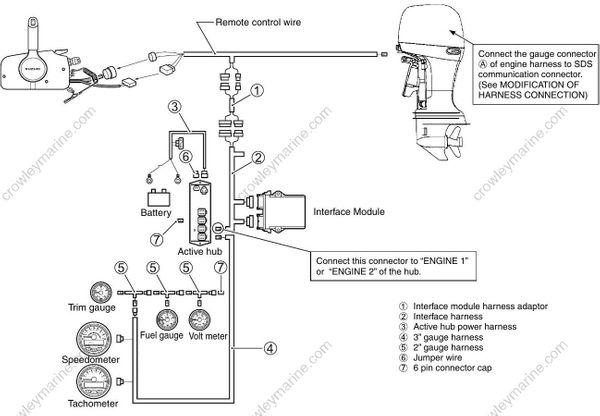
For operating the digital gauge, disconnect the gauge connector (A) from gauge connector (B), and connect the gauge connector (A) to the SDS communication connector as shown in the illustration.
DIGITAL GAUGE AND RELATED PARTS CONNECTION
• In the case that the wiring harness gauge connector is connected to the SDS communication connector, SDS (SUZUKI Diagnosis System) cannot be used.
• When SDS has to be used, disconnect the SDS communication connector from the gauge connector.
• When SDS is being used, the digital gauge system cannot be operated.
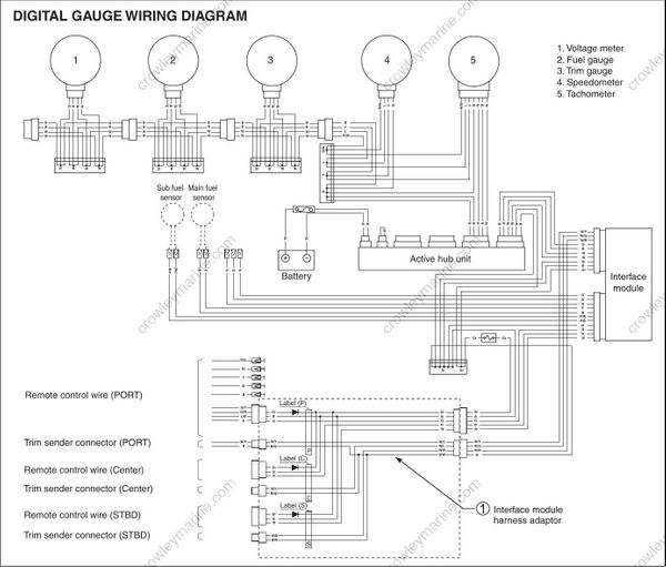
• The remote control wire should be connected to the interface module harness adaptor with the specified connector as shown below. If the remote control wire is not connected to the specified connector of the interface module harness, the meter will not function properly.
• Single engine: Connect to label (P) connector.
• Twin engine:
PORT engine: Connect to label (P) connector.
STBD engine: Connect to label (S) connector.
SET-UP OF TACHOMETER
Each tachometer should be set up according to the applicable engine.
If the setting is incorrect, the tachometer does not function as required. Default value of the tachometer is “SETUP Eng Position 0”.
Set up the tachometer in the following procedure.
(1) Turn ON the ignition switch.
(2) Press the “∆” and “∇” buttons to display “System Setup” on the LCD.
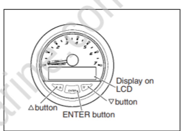
(3) Press the “ENTER” button.
(4) “SETUP Contrast” is displayed on the LCD.
(5) Press the “∇” button once to display “SETUP Eng Position” on the LCD.
(6) By pressing the “ENTER” button, “SETUP Eng Position 0” is displayed on the LCD.
At this condition, press the “∆” and “∇” buttons. Display on the LCD is changed as shown in the right figure.
Display the required engine on the LCD and press the “ENTER” button to define.
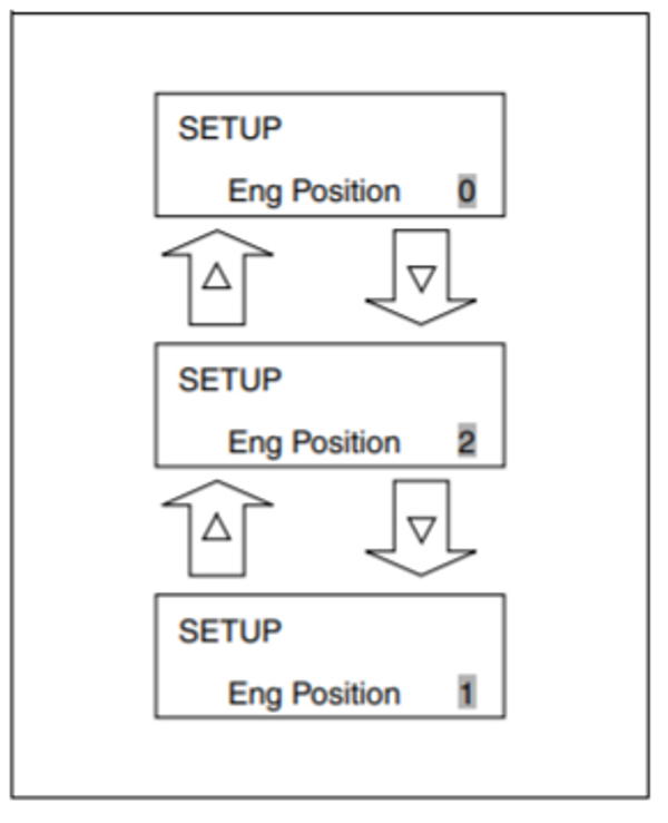
Single engine
Set to “Eng Position 0”.
Dual engine
PORT outboard motor: Set to “Eng Position 0”. STBD outboard motor: Set to “Eng Position 1”.
Triple engine
PORT outboard motor: Set to “Eng Position 0”.
CENTER outboard motor: Set to “Eng Position 1”.
STBD outboard motor: Set to “Eng Position 2”.
By pressing the “ENTER” button for more than 3 seconds, “System Setup” menu returns.
(7) Start the engines in succession from the one on the PORT side and check that the tachometers work according to the engines.
TACHOMETER · MONITOR
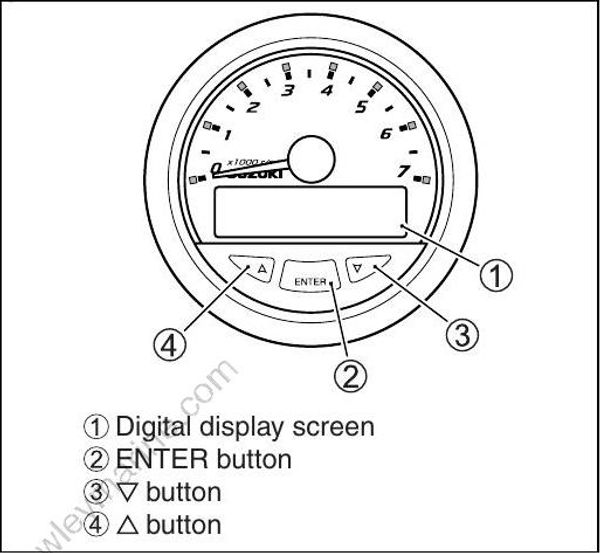
DIGITAL DISPLAY SCREEN
The digital display screen can indicate the following engine information.
Engine RPM
Engine Temperature
Engine operation hours
Atmospheric pressure
Fuel rate : Lit. or Gallons per hour
Intake manifold pressure
Trim Angle
Battery Voltage
Shift position
CAUTION name (When problem is detected)
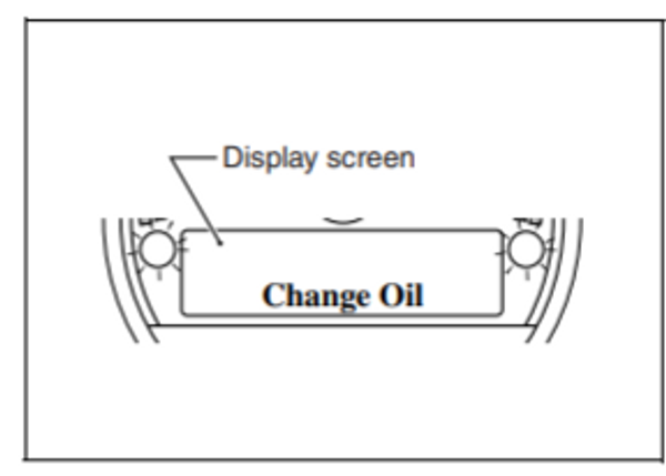
Oil change reminder (When the total motor operating hours have reached pre programmed hours)
Self-Diagnostic code (When problem is detected) NOTE:
• The items of No. 1 – 8 can be selected by pressing “ENTER” or / button. (For details, see Meter operation manual.) Pressing “ENTER” or / button once changes the displayed data.
• When the ignition key is turned from OFF to ON:
• A caution buzzer will sound for two seconds.
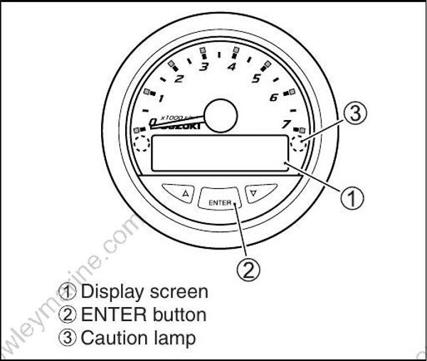
• Two caution lamps also turns on for two seconds.
• The tachometer needle swings up then returns to zero (0) rpm.
• The total operating hours displayed are those of actual engine operation, not ignition switch “ON” time.
• The Caution information and Self-Diagnostic information shown in the display screen can be deleted by pressing “ENTER” button.
When more than one information occur at the same time, press “ENTER” button to read the next information. Even though deleting the information from the display screen, both the caution lamp and buzzer remain on until the problems have been solved.
TACHOMETER DISPLAY INDICATION
CAUTION SYSTEM
When a problem is detected, the caution name appears on the display screen of tachometer-monitor, caution buzzer sounds and caution lamps lights continuously.
| CAUTION TYPE | TACHOMETER DISPLAY INDICATION |
|---|---|
| Over-revolution | Rev Limit [ NOTE 1] |
| Low oil pressure | Over Revolution [NOTE 2] |
| Low oil pressure | Low Oil Pressure |
| Over heat | Over Heat |
| Low battery voltage | Low Batt Voltage |
1: When the engine speed detected by ECM exceeds the preset maximum engine speed.
2: Engine is continuously operated with the over-revolution limiter that exceeds the preset maximum engine speed for more than 10 seconds.
SELF-DIAGNOSTIC SYSTEM
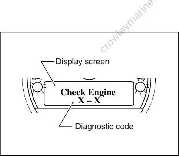
When an abnormality occurs in a signal from sensor, switch, etc., the diagnostic code appears on the display screen of tachometer-monitor, caution buzzer sounds and caution lamps lights continuously.
When engine is not running, the buzzer sounds according to self-diagnostic code pattern.
• When two or more failures have occurred at the same time, the caution buzzer beeps three times repeatedly in the order of descending priorities according to the diagnostic code pattern (while the engine is standstill with the ignition switch in ON).
• In the display screen, the following diagnostic code information appears when “ENTER” button is pressed. This information is shown in the order of occurrence.
OIL CHANGE REMINDER SYSTEM
When the total motor operating hours have reached the preprogrammed hours, the Change Oil appears on the display screen of tachometer-monitor, caution buzzer sounds if engine is not running (but ignition switch ON) and caution lamps lights continuously.