DISASSEMBLY
Before disassembling:
Remove the power unit. (See the page 6-6.)
Remove the cylinder head assy. (See the page 6-14.)
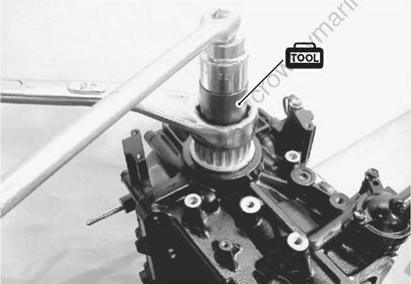
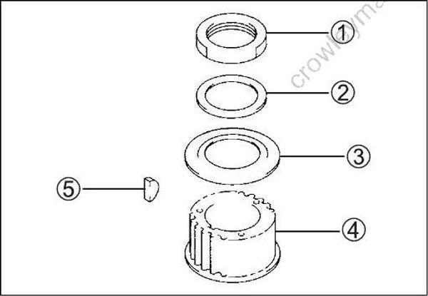
- Remove the timing pulley nut (1).
09911-49910: Crankshaft holder
Remove the washer (2), the guide (3), the timing pulley (4) and the key (5).
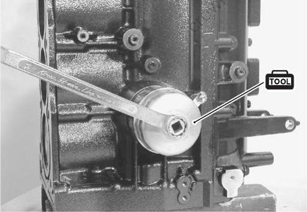
- Remove the oil filter.
09915-47341: Oil filter wrench
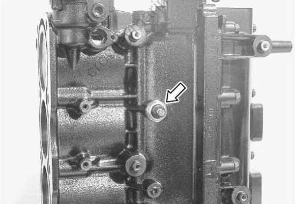
- Remove the oil pressure switch.
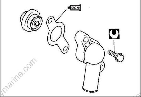
- Remove the three bolts, the thermostat cover, the gasket, the thermostat and the stopper plates.
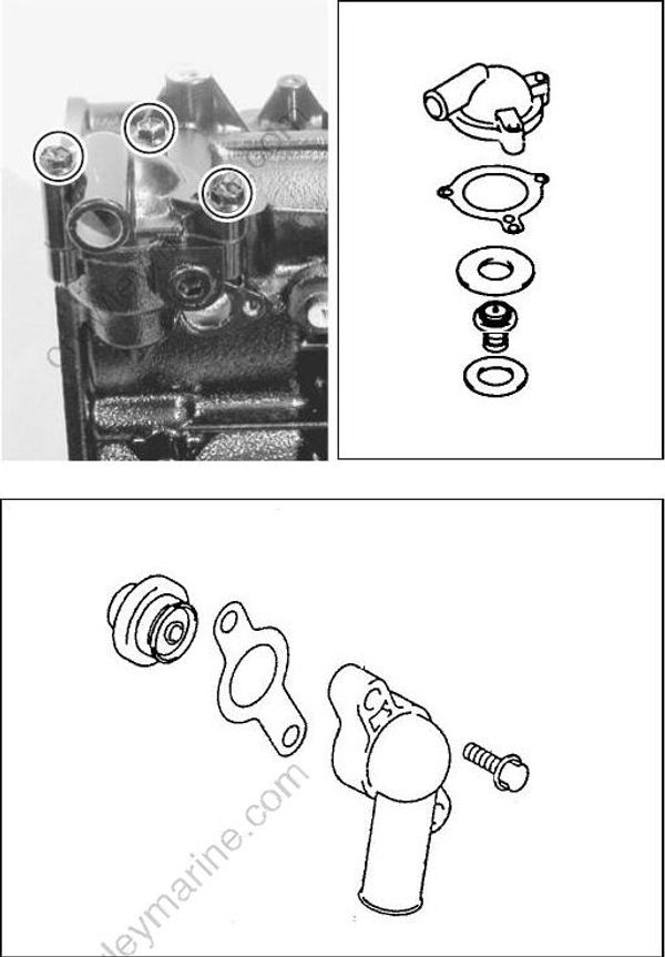
Remove the two bolts, the water pressure valve cover, the gasket and the water pressure valve from the exhaust manifold.
Remove the ten M10-bolts (1).
Remove the ten M8-bolts (2).
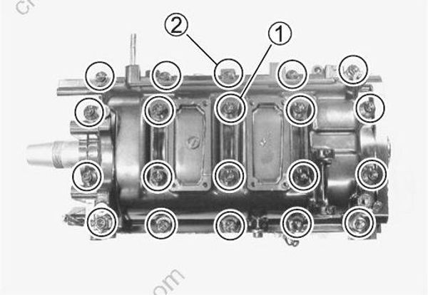
- Remove the crankcase from the cylinder block.
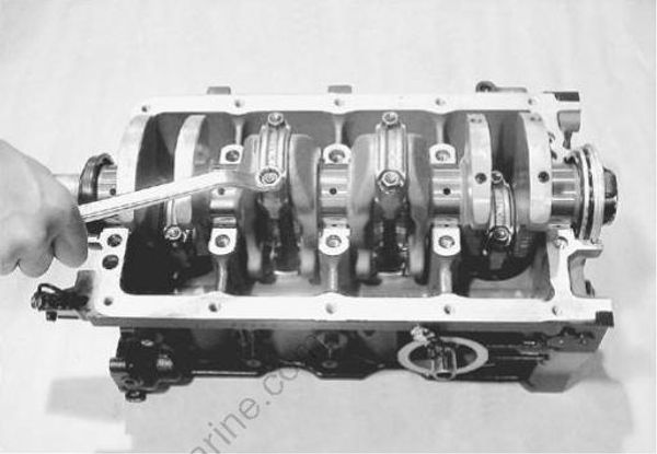
For proper assembly, mark the cylinder number on all conrod caps using quick dry paint.
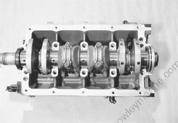
- Remove all conrod cap nuts and conrod caps.
Reassemble each conrod cap to its original position
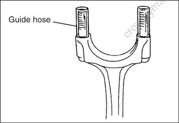
To prevent damage to the crank pin and the bolt threads, install a guide hose over the threads of the conrod bolts.
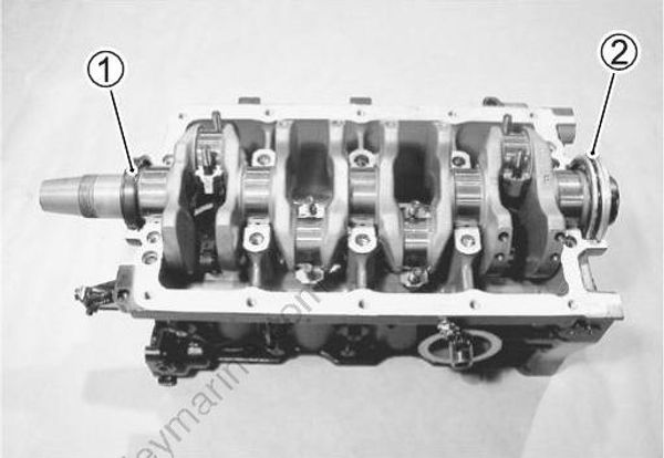
Remove the crankshaft.
Remove the oil seal (1) and the oil seal housing (2) from the crankshaft.
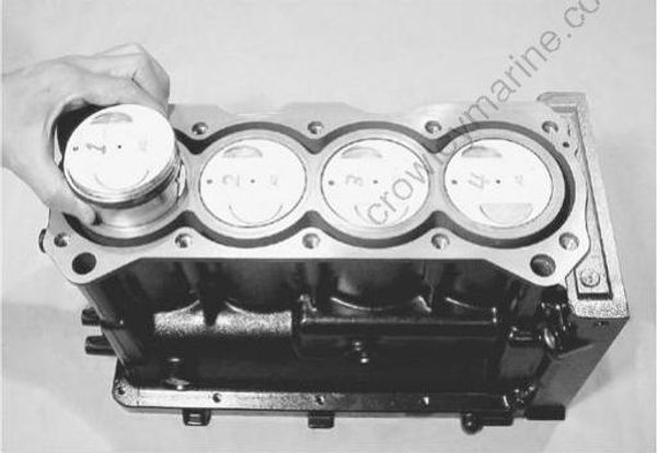
- Remove the pistons with the conrod.
• For proper assembly, mark cylinder number on all conrods and pistons using quick dry paint.
• To prevent damage to the piston rings, decarbon from the cylinder bore wall before removing the piston.
- Remove all piston rings.
Install the 1st ring to the piston with its original direction.
There is no I.D. mark on the standard size 1st ring.
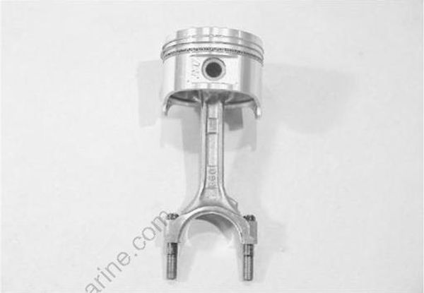
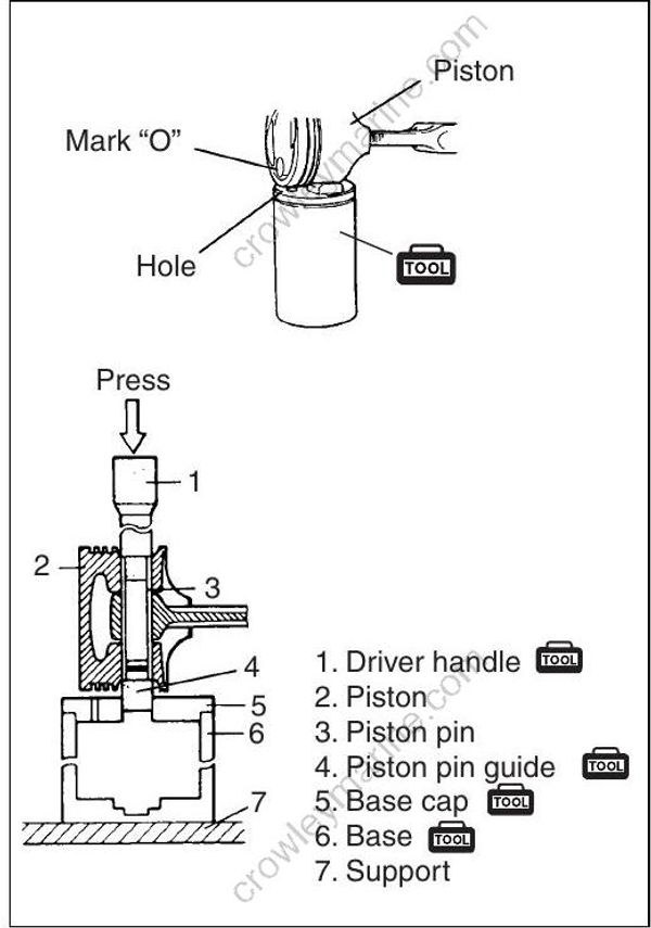
- Remove the piston pin from the piston and the conrod using the tool and an arbor press as shown.
09910-38211: Piston pin remover & installer
Reassemble each piston, piston pin and conrod with their original combination and position.
INSPECTION/SERVICING
If excessive wear, cracks, defective or other damage is found on any component, replace component.
CYLINDER/PISTON
Cylinder distortion
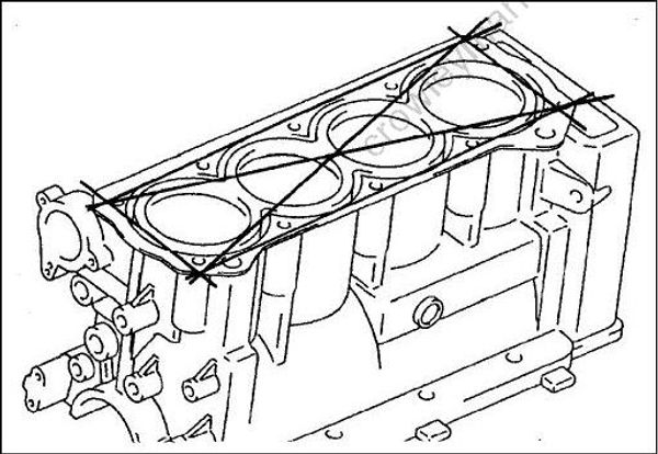
Measure the cylinder distortion (gasketed surface) at a total of 6 locations as shown.
09900-20803: Thickness gauge
Straight gauge
Service limit: 0.060 mm (0.0024 in)
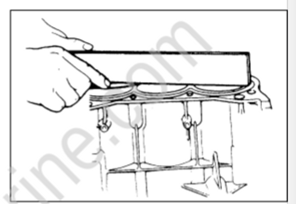
If the measurement exceeds the service limit, resurface or replace the cylinder.
The cylinder can be resurfaced, using a surface plate and #400 grit wet sandpaper. Move the cylinder in a figure eight pattern when sanding.
Water jacket
Check the water jackets.
If clog or obstruction is found, clean the water jacket.
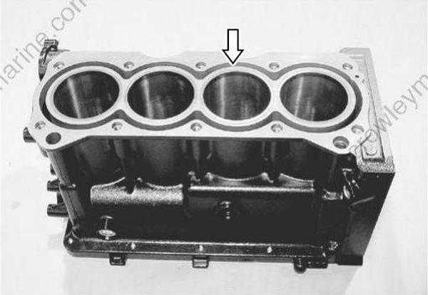
Cylinder bore wear (difference)
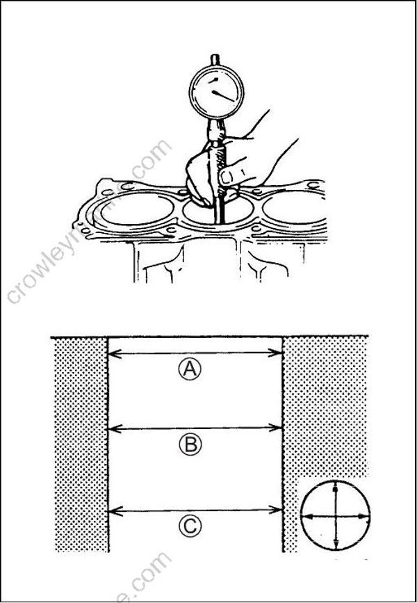
Measure the cylinder bore in the thrust and axial directions at the three positions (A), (B) and (C) as shown.
Check for the followings:
Difference of the measurements at the two positions. (Taper)
Difference between the thrust and axial measurement. (Out-of-round)
09900-20530: Cylinder gauge set
Service limit: 0.100 mm (0.0039 in)
If the measurement exceeds the service limit, rebore or replace the cylinder.
Piston to cylinder clearance
Standard: 0.020 – 0.040 mm (0.0008 – 0.0016 in)
Service limit: 0.100 mm (0.0039 in)
If the measurement exceeds the service limit, replace the piston and/or the cylinder or rebore the cylinder.
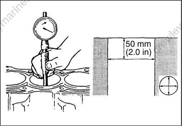
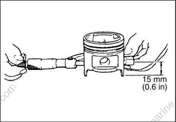
To check the clearance, measure the following items:
Cylinder bore at 50 mm elevation from the gasketed surface
Piston skirt diameter at 15 mm elevation from the skirt end
09900-20530: Cylinder gauge set
09900-20203: Micrometer
Standard:
| Cylinder bore | Piston skirt diameter |
|---|---|
| 74.000 – 74.020 mm (2.9134-2.9142 in) |
73.970 – 73.990 mm (2.9122-2.9130 in) |
For this check, measure the cylinder bore and the piston skirt diameter in the direction that makes a right angle with the crankshaft (piston pin)
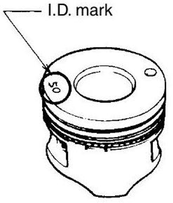
Identification of oversize piston/piston ring
Piston
| Oversize | I.D. mark |
|---|---|
| 0.50 mm (0.020 in) | 0.50 |
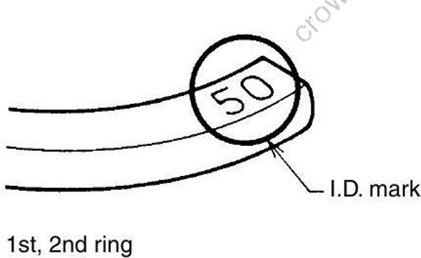
1st & 2nd ring
| Oversize | I.D. mark |
|---|---|
| 0.50 mm (0.020 in) | 50 |
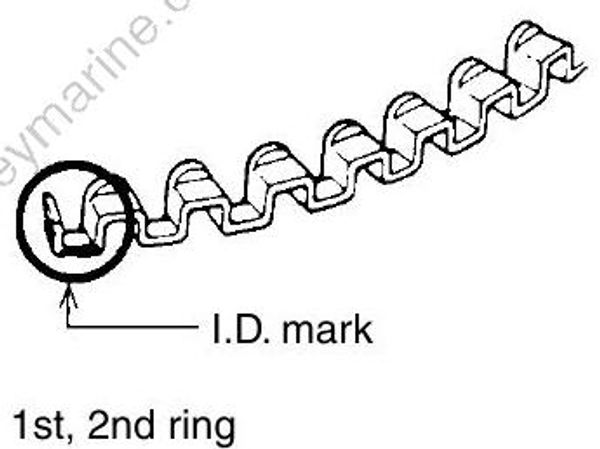
Oil ring
| Oversize | I.D. mark |
|---|---|
| 0.50 mm (0.020 in) | Red paint |
For the oil ring side rail, measure the outer diameter of the rail to distinguish because there is no I.D. mark.
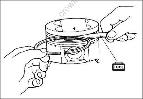
Piston ring to groove clearance
Measure the clearance after decarboning.
09900-20803: Thickness gauge
Standard:
1st 0.03 – 0.07 mm (0.001 – 0.003 in)
2nd 0.02 – 0.06 mm (0.001 – 0.002 in)
Service limit:
1st 0.12 mm (0.005 in)
2nd 0.10 mm (0.004 in)
If the measurement exceeds the service limit, replace the piston and/or the piston ring.
Standard:
| Piston ring groove width | Piston ring thickness | |
|---|---|---|
| 1st | 1.22 – 1.24 mm(0.048 – 0.049 in) | 1.17 – 1.19 mm(0.046 – 0.047 in) |
| 2nd | 1.51 – 1.53 mm(0.059 – 0.060 in) | 1.47 – 1.49 mm(0.058 – 0.059 in) |
| Oil | 2.81 – 2.83 mm(0.111 – 0.112 in) | —— |
09900-20102: Vernier calipers
09900-20205: Micrometer
Piston ring end gap
Measure the piston ring end gap with the piston ring in the low est position of the cylinder bore.
09900-20803: Thickness gauge
Standard:
1st 0.15 – 0.30 mm (0.006 – 0.012 in)
2nd 0.20 – 0.35 mm (0.008 – 0.014 in)
Service limit: 1st & 2nd 0.70 mm (0.028 in)
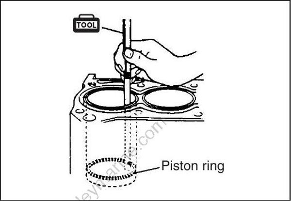
If the measurement exceeds the service limit, replace the piston ring.
Piston ring free end gap
Measure the piston ring free end gap.
09900-20102: Vernier calipers
Standard:
1st Approx. 7.7 mm (0.30 in)
2nd Approx. 10.4 mm (0.41 in)
Service limit:
1st 6.1 mm (0.24 in)
2nd 8.3 mm (0.33 in)
If the measurement is lower than the service limit, replace the piston ring.
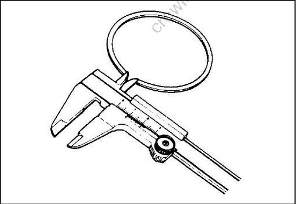
Piston pin oil clearance
Check for the followings:
The piston pin and the piston pin hole are free from excessive wear and damage.
The piston pin can move smoothly in the piston pin hole with oil.
If the result is not the above conditions, replace the piston pin and/or the piston.
Standard: 0.003 – 0.016 mm (0.0001 – 0.0006 in)
Service limit: 0.040 mm (0.0016 in)
If the measurement exceeds the service limit, replace the piston pin and/or the piston.
To check the clearance, measure the following items:
Piston pin outside diameter in the thrust and axial directions.
Piston pin hole diameter in the thrust and axial directions.
09900-20205: Micrometer
09900-20605: Dial calipers
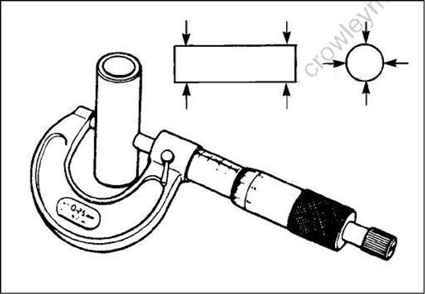
Standard:
| Piston pin outside diameter | Piston pin hole diameter |
|---|---|
| 16.995 – 17.000 mm (0.6691 – 0.6693 in) | 17.003 – 17.011 mm (0.6694 – 0.6697 in) |
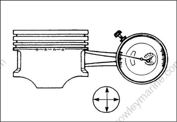
Conrod small end inside diameter
Measure the conrod small end inside diameter.
09900-20605: Dial calipers
Standard: 16.968 – 16.979 mm (0.6680 – 0.6685 in)
If the measurement is out of the specification, replace the con rod.
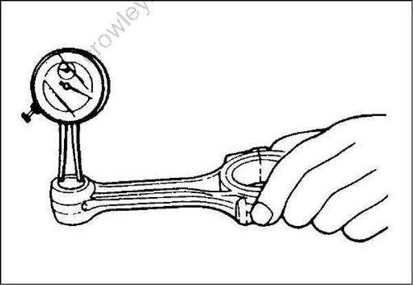
The piston pin is press-fitted into the conrod small end hole.
There must be a negative clearance between the two items.
CONROD/CRANKSHAFT/CRANKCASE
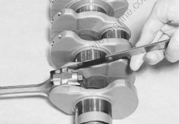
Conrod big end side clearance
Measure the conrod big end side clearance with the conrod installed on the crank pin as shown.
09900-20803: Thickness gauge
Standard: 0.10 – 0.25 mm (0.004 – 0.010 in)
Service limit: 0.35 mm (0.014 in)
If the measurement exceeds the service limit, replace the con rod and/or the crankshaft.
Standard:
| Conrod big end width | Crank pin width |
|---|---|
| 21.95 – 22.00 mm (0.864 – 0.866 in) | 22.10 – 22.20 mm (0.870 – 0.874 in) |
09900-20205: Micrometer
09900-20605: Dial calipers
Crank pin outside diameter/difference
Measure the crank pin outside diameter in the thrust and axial directions at the two positions as shown. Check for the followings:
Difference of the measurements at the two positions. (Taper)
Difference between the thrust and axial measurement. (Out-of-round)
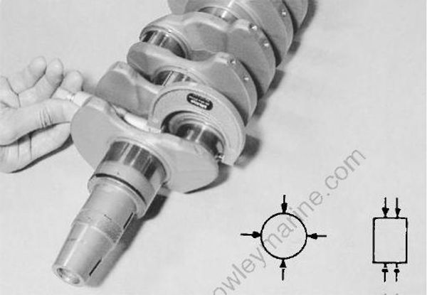
09900-20202: Micrometer
Service limit: 0.010 mm (0.0004 in)
If the measurement exceeds the service limit, replace the crank shaft.
Crank pin outside diameter:
Standard: 41.982 – 42.000 mm (1.6528 – 1.6535 in)
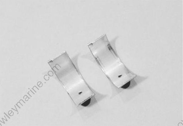
Conrod bearing condition
If pitting, flaking, burn or excessive wear is found, replace the conrod bearing.
Conrod big end oil clearance
Standard: 0.020 – 0.050 mm (0.0008 – 0.0020 in)
Service limit: 0.080 mm (0.0031 in)
If the measurement exceeds the service limit, replace the con rod bearing.
Measure the conrod big end oil clearance as follows:
Clean the surface of the conrod, the conrod cap, the conrod bearing, and the crank pin.
Install the conrod bearing onto the conrod and the conrod cap.
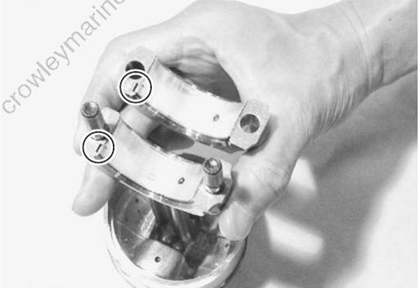
• Reassemble each bearing, conrod cap to their original position.
• Do not apply oil to the bearing.
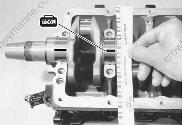
- Place a piece of the plastigauge on the crank pin with parallel to the crankshaft, avoiding the oil hole.
09900-22301: Plastigauge
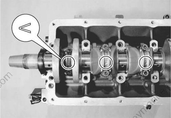
Install the conrod cap (with the bearing) to the conrod with the arrow mark on the cap toward the flywheel side.
Apply engine oil to the conrod bolts and tighten the nuts by the two steps.
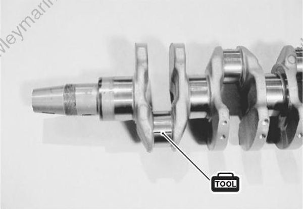
Conrod cap nut:
Primary 18 N·m (1.8 kg-m, 13.0 lb-ft)
Secondary 35 N·m (3.5 kg-m, 25.5 lb-ft)
Do not rotate the conrod with the plastigauge in place.
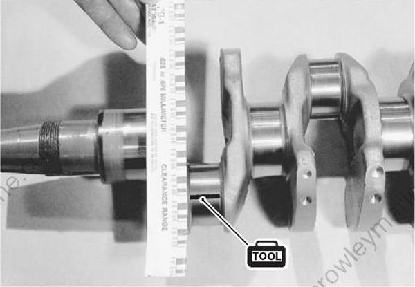
- Remove the conrod, the conrod cap and the bearing from the crank pin.
- Measure the compressed plastigauge width at its widest point.
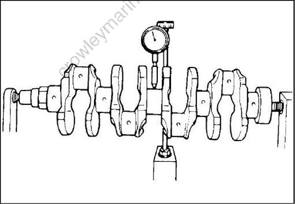
Crankshaft center journal runout
Measure the crankshaft center journal runout.
09900-20602: Dial gauge
09900-20701: Magnetic stand
Service limit: 0.06 mm (0.002 in)
If the measurement exceeds the service limit, replace the crank shaft.
Crankshaft thrust clearance
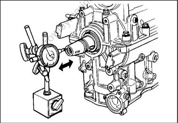
Measure the crankshaft thrust clearance as shown, after installing the crankshaft bearing, the thrust bearing, the crankshaft and the crankcase to the cylinder in the normal manner.
09900-20602: Dial gauge
09900-20701: Magnetic stand
Standard: 0.11 – 0.31 mm (0.004 – 0.012 in)
Service limit: 0.38 mm (0.015 in)
If the measurement exceeds the service limit, replace the crank shaft thrust bearing.
Crankshaft thrust bearing thickness:
Standard: 2.47 – 2.52 mm (0.097 – 0.099 in)
Crankshaft journal outside diameter/difference
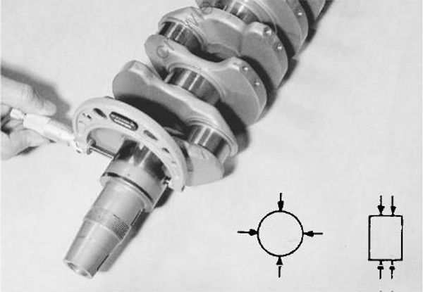
Measure the crankshaft journal outside diameter in the thrust and axial directions at the two positions as shown. Check for the followings:
Difference of the measurements at the two positions. (Taper)
Difference between the thrust and axial measurement. (Out-of-round)
09900-20203: Micrometer
Service limit: 0.010 mm (0.0004 in)
If the measurement exceeds the service limit, replace the crank shaft.
Crankshaft journal outside diameter:
Standard: 51.982 – 52.000 mm (2.0465 – 2.0472 in)
Crankshaft bearing condition
If pitting, flaking, burn or excessive wear is found, replace the bearing.
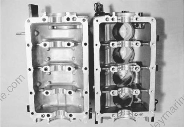
Crankshaft journal oil clearance
Standard: 0.016 – 0.036 mm (0.0006 – 0.0014 in)
Service limit: 0.060 mm (0.0024 in)
If the measurement exceeds the service limit, replace the crank shaft bearing.
Measure the crankshaft journal oil clearance as follows:
Clean the surface of the bearing holder (crankcase and cylinder), the bearing and the bearing journal.
Install the crankshaft bearing to the cylinder and the crank case.
• Reassemble each bearing to its original position.
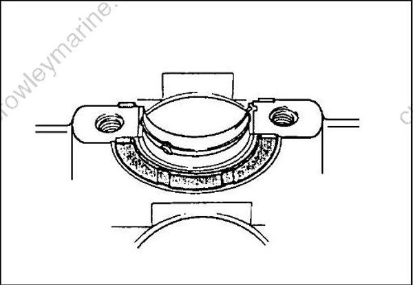
• Install the half of bearing with the oil hole to the cylinder side.
• Align the tab (a) of the bearing with the notch in the cylinder and the crankcase.
• Do not apply oil to the bearing
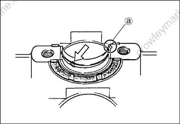
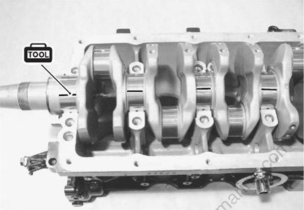
Install the crankshaft to the cylinder.
Place a piece of the plastigauge on the journal with parallel to the crankshaft, avoiding the oil hole.
09900-22301: Plastiguage
Install the crankcase (with the bearing) to the cylinder.
Apply the engine oil to the crankcase bolts and tighten the bolts by the three steps.
Crankcase bolt:
1st step
8 mm 5 N.m (0.5 kg-m, 3.5 lb-ft)
10 mm 10 N.m (1.0 kg-m, 7.0 lb-ft)
2nd step
8 mm 20 N.m (2.0 kg-m, 14.5 lb-ft)
10 mm 40 N.m (4.0 kg-m, 29.0 lb-ft)
Final step
8 mm 25 N.m (2.5 kg-m, 18.0 lb-ft)
10 mm 50 N.m (5.0 kg-m, 36.0 lb-ft)
• The crankcase should be torqued to the specification in order to assure proper compression of the plastigauge and accurate reading of the clearance.
• Do not rotate the crankshaft with the plastigauge in place.
- Remove the crankcase from the cylinder.
- Measure the compressed plastigauge width at its widest point.
For bearing replacement, see the “CRANKSHAFT/CRANKCASE COMBINATION” section on the page 6-42.
CRANKSHAFT/CRANKCASE COMBINATION
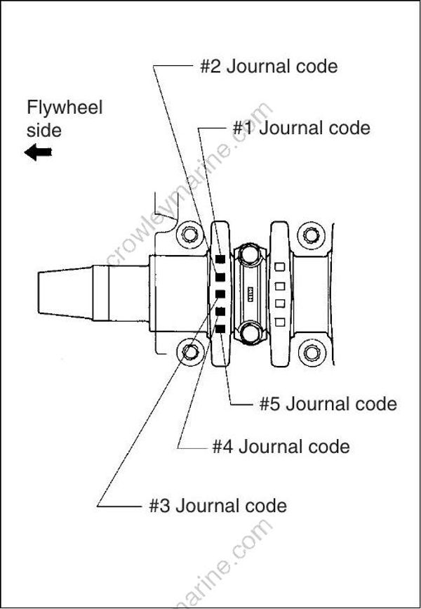
Crankshaft journal outside diameter code
The codes are stamped on the upper (flywheel side) web of the crankshaft as shown.
Standard:
| Code | Crankshaft journal outside diameter |
|---|---|
| 1 | 51.994 – 52.000 mm (2.0470 – 2.0472 in) |
| 2 | 51.988 – 51.944 mm (2.0467 – 2.0470 in) |
| 3 | 51.982 – 51.988 mm (2.0465 – 2.0467 in) |
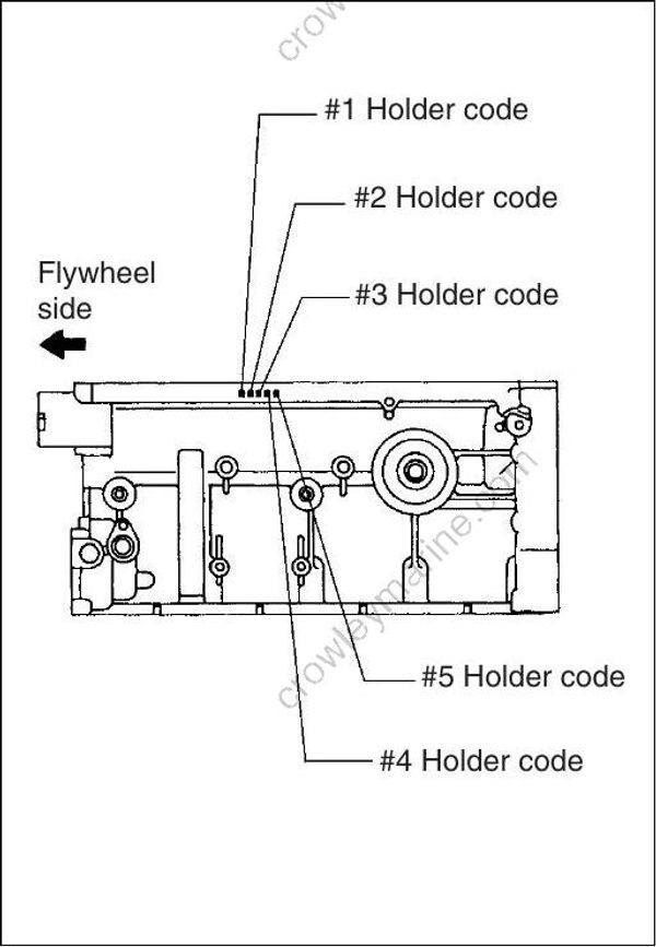
Crankcase bearing holder inside diameter code
The codes are stamped on the starboard side of the cylinder block as shown.
Standard:
| Code | Crankcase bearing holder inside diameter |
|---|---|
| A | 56.000 – 56.006 mm (2.2047 – 2.2050 in) |
| B | 56.006 – 56.012 mm (2.2050 – 2.2052 in) |
| C | 56.012 – 56.018 mm (2.2052 – 2.2054 in) |
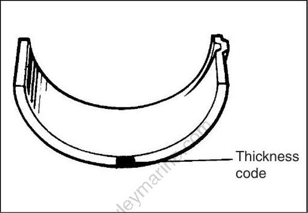
Crankshaft bearing thickness code
The codes are painted on the side of the bearing as shown.
Standard:
| Code | Crankshaft bearing thickness |
|---|---|
| Green | 1.998 – 2.002 mm (0.0787 – 0.0788 in) |
| Black | 2.001 – 2.005 mm (0.0788 – 0.0789 in) |
| No paint | 2.004 – 2.008 mm (0.0789 – 0.0791 in) |
| Yellow | 2.007 – 2.011 mm (0.0790 – 0.0792 in) |
| Blue | 2.010 – 2.014 mm (0.0791 – 0.0793 in) |
Crankshaft bearing selection
Select the crankshaft bearing referring the below table. Bearing selection table
| Crankshaft journal outside diameter | Crankshaft journal outside diameter | Crankshaft journal outside diameter | ||
|---|---|---|---|---|
| Code | 1 | 2 | 3 | |
| Crankcase bearing holder inside diameter | A | Green | Black | No paint |
| Crankcase bearing holder inside diameter | B | Black | No paint | Yellow |
| Crankcase bearing holder inside diameter | C | No paint | Yellow | Blue |
Remeasure the crankshaft journal oil clearance using new bearings selected. (See the page 6-40.)
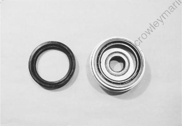
OIL SEAL
If crack, cut or other damage is found, replace.
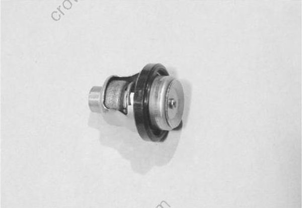
THERMOSTAT
If deposited salt, corrosion, wear or other damage is found, clean or replace.
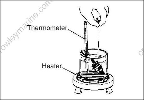
Thermostat operation
Check the thermostat opening temperature as follows.
Insert a length of thread between the thermostat valve/body and suspend the thermostat in a container filled with water.
Place the thermometer in the container and heat water. Observe water temperature when the thermostat valve opens and releases the thread.
Thermostat operating temperature:
Standard: 58 – 62 °C (136 – 144 °F)
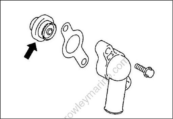
WATER PRESSURE VALVE
If deposited salt, corrosion, wear or other damage is found, clean or replace.
REASSEMBLY
Reassembly is reverse order of disassembly with the special attention to the following steps.
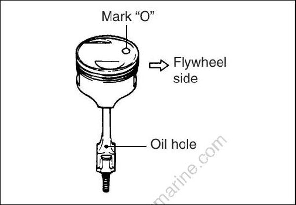
PISTON TO CONROD
- Apply the engine oil to the piston pin holes and the conrod. Make sure that the conrod is installed with the direction as shown.
Reassemble each piston, piston pin and conrod with their original combination and position.
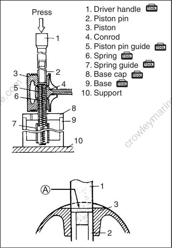
- Press fit the piston pin to the conrod (with the piston) until the line (A) on the driver handle flush with the flat surface of the piston, using the tool and an arbor press as shown.
09910-38211: Piston pin remover & installer
PISTON RING TO PISTON
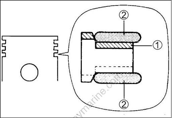
Oil ring
Apply the engine oil to the piston rings.
Install the spacer (1) first, then the side rails (2) to the piston.
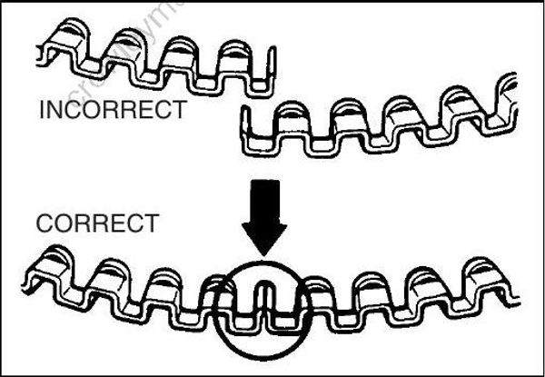
When installing the spacer, do not allow its two ends to overlap in the groove.
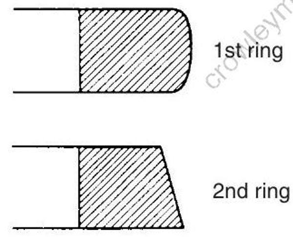
1st ring and 2nd ring
Apply the engine oil to the piston rings.
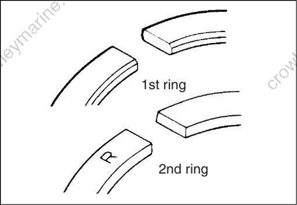
Install the 2nd ring and the 1st ring to the piston.
• Install the 2nd ring to the piston with the “R” mark toward the piston head side.
• Install the 1st ring to the piston with its original direction.
• There is no I.D. mark on the standard size 1st ring.
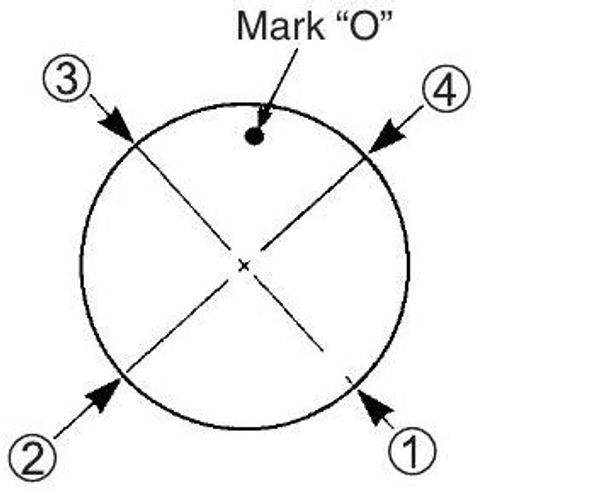
Ring gap direction
Position the rings so that their gaps are stagged at approximately 90 degree angles as shown.
(1) 1st ring
(2) Oil ring lower side rail
(3) 2nd ring
(4) Oil ring upper side rail
PISTON TO CYLINDER
- Install the conrod bearing to the conrod and the conrod cap.
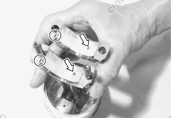
• Reassemble each conrod bearing to its original position.
• Install the half of the bearing with the oil hole to the conrod side.
• Do not apply oil to the back of the bearing.
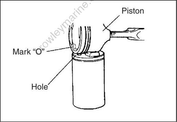
Apply the engine oil to the piston and cylinder bore wall.
Insert piston (with conrod) to cylinder from head side using the tool.
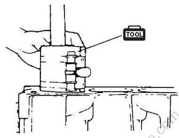
09916-77310: Piston ring compressor
Position the CIRCLE mark on the piston head to the flywheel side.
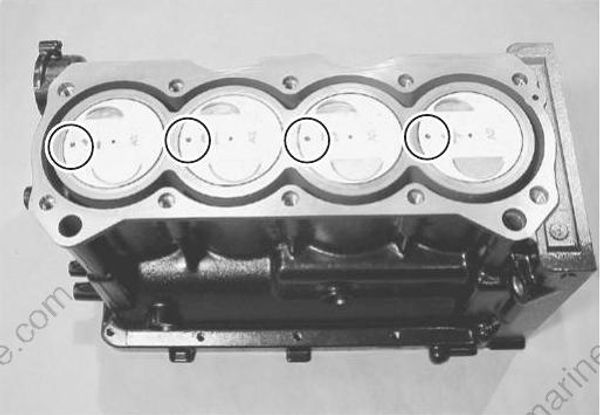
CRANKSHAFT TO CYLINDER
Install the crankshaft bearings to the cylinder and the crank case.
Apply the engine oil to the bearings.
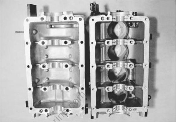
• Reassemble each bearing to its original position.
• Install the half of the bearing with the oil hole to the cylinder side.
• Do not apply oil to the back of the bearing.
Align the tab (a) of the bearing with the notch in the cylinder and the crankcase
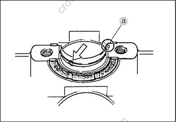
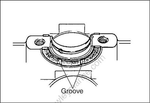
- Install the crankshaft thrust bearings to the cylinder.
Install the thrust bearing with its groove facing outward.
Apply the engine oil to the lip area of the upper oil seal.
Install the upper oil seal and the lower oil seal housing to the crankshaft.
Do not re-use the seal once removed. Always use a new seal.
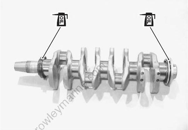
Install the upper oil seal with its spring/lipped side facing inward.
- Install the crankshaft to the cylinder.
When installing the crankshaft to the cylinder, be sure to fit the tabs of the seal and the housing in the grooves of the cylinder.
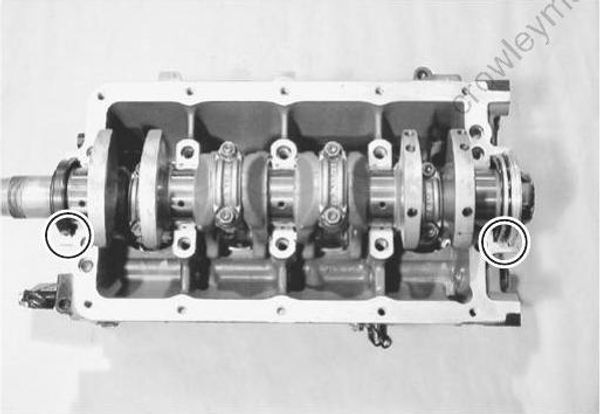
Apply the engine oil to the crank pins and the conrod bearings.
Install the conrod cap (with the bearing) to the conrod with the arrow mark on the cap toward the flywheel side.
Reassemble each conrod cap to its original position.
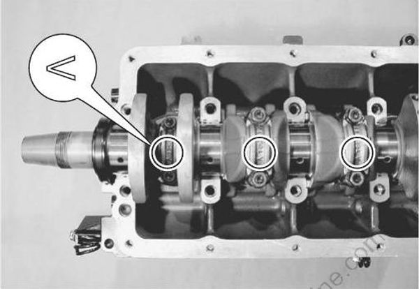
Apply the engine oil to the conrod bolts.
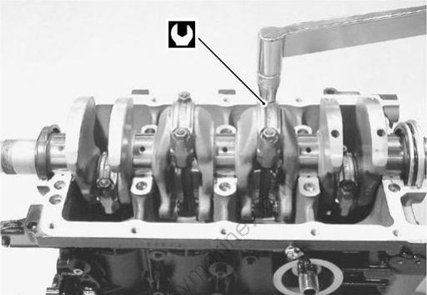
Tighten the nuts by the two steps.
Conrod cap nut:
1st step 18 N.m (1.8 kg-m, 13.0 lb-ft)
Final step 35 N.m (3.5 kg-m, 25.5 lb-ft)
CRANKCASE TO CYLINDER
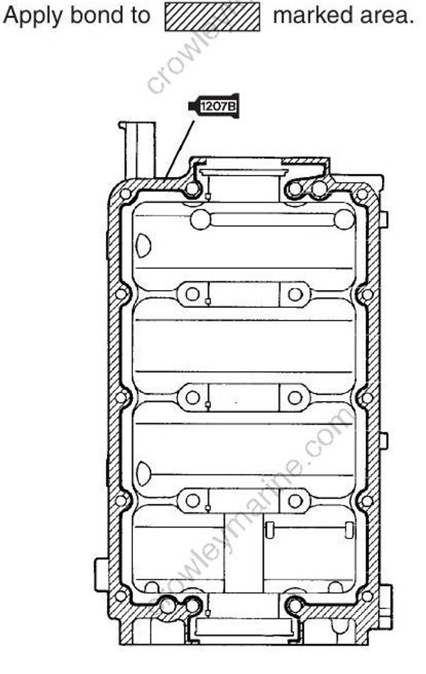
Clean the mating surface of the cylinder and the crankcase.
Apply the bond to the mating surface of the crankcase as shown.
99000-31140: SUZUKI BOND “1207B”
Apply the bond to the mating surface avoiding the bearing with the bond.
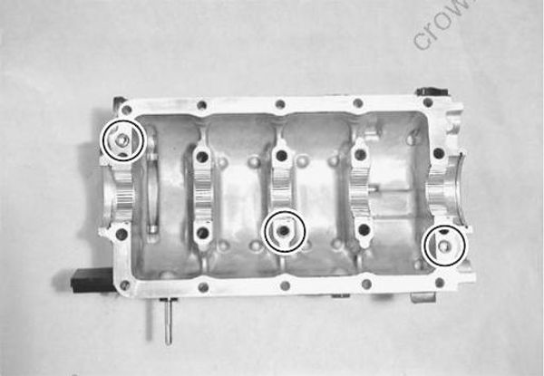
- Install the three dowel pins.
Install the crankcase (with the bearing) to the cylinder.
Apply the engine oil lightely to the crankcase bolts.
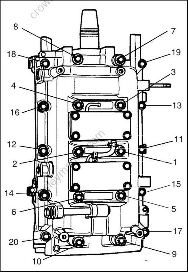
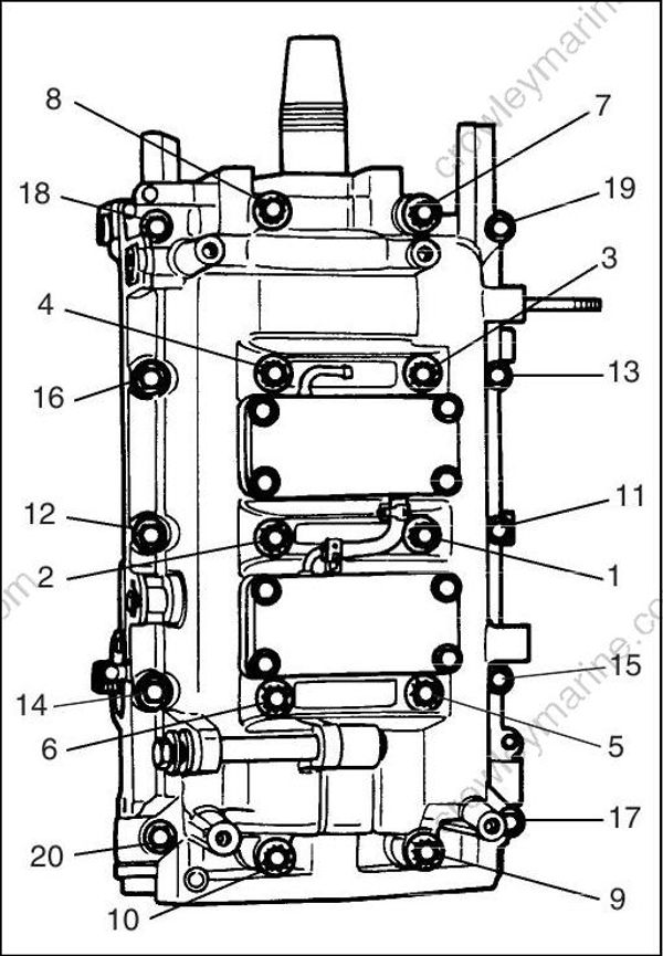
Tighten the twenty bolts by the three steps according to the numerical order as shown.
Crankcase bolt:
1st step
8 mm 5 N.m (0.5 kg-m, 3.5 lb-ft)
10 mm 10 N.m (1.0 kg-m, 7.0 lb-ft)
2nd step
8 mm 20 N.m (2.0 kg-m, 14.5 lb-ft)
10 mm 40 N.m (4.0 kg-m, 29.0 lb-ft)
Final step
8 mm 25 N.m (2.5 kg-m, 18.0 lb-ft)
10 mm 50 N.m (5.0 kg-m, 36.0 lb-ft)
TIMING PULLEY
- Install the key (2), the timing pulley (3), the upper guide (1), and the washer (4) to the crankshaft.
Make sure that the guide 1 and the washer (4) are installed with the direction as shown.
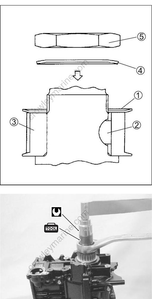
- Tighten the timing pulley nut 5 to the specified torque.
09911-49910: Crankshaft holder
Timing pulley nut: 70 N·m (7.0 kg-m, 50.5 lb-ft)
THERMOSTAT
Install the thermostat, the gasket and the cover by the three bolts.
Do not re-use the gasket once removed. Always use a new gasket.
Thermostat cover bolt: 10 N·m (1.0 kg-m, 7.0 lb-ft)
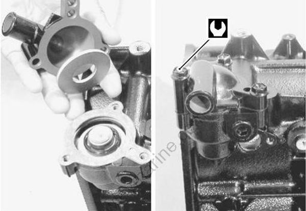
WATER PRESSURE VALVE
- Apply the bond to both surfaces of the gasket in its mating area.
99000-31140: SUZUKI BOND “1207B”
- Install the water pressure valve, the gasket and the cover by the two bolts.
Do not re-use the gasket once removed. Always use a new gasket.
Water pressure valve cover bolt: 10 N·m (1.0 kg-m, 7.0 lb-ft)