

Precautions
Precaution for Manual Starting System
Failure to take proper precautions when servicing the recoil starter can cause personal injury.
Wear safety glasses and hand protection when winding or unwinding this component.
General Description
Manual Starting System
The manual starter engages the flywheel ratchet with two pawls when the starter grip is pulled.
A recoil spring is wound as the starter rope pulls and rewinds as the starter grip is returned to the case.
The reel stopper linked to the clutch shaft prevents accidental manual starter engagement while the motor is in gear.
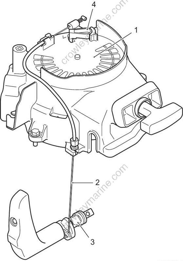
| 1.Recoil starter | 3.Clutch shaft |
|---|---|
| 2.NSI cable | 4.Reel stopper |
Service Instructions
Recoil Starter Components


Recoil Starter Removal and Installation
Removal
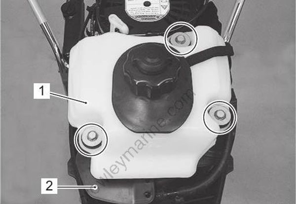
1) Remove the fuel tank (1).
Refer to “Fuel Tank Removal and Installation” in Section 1G (Page 1G-19).
2) Remove the fuel tank plate (2).
Refer to “Fuel Tank Removal and Installation” in Section 1G (Page 1G-19).
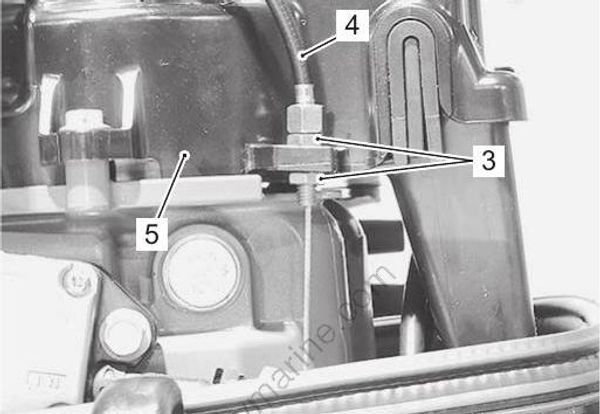
3) Loosen the lock nuts (3) and remove the NSI cable (4) from the recoil starter (5).
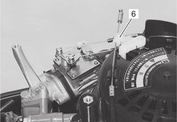
4) Remove the NSI cable from the reel stopper (6) and the recoil starter.
5) Shift into “Forward” position.
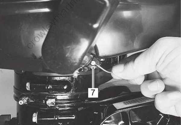
6) Remove the NSI cable from the clutch notch plate (7).
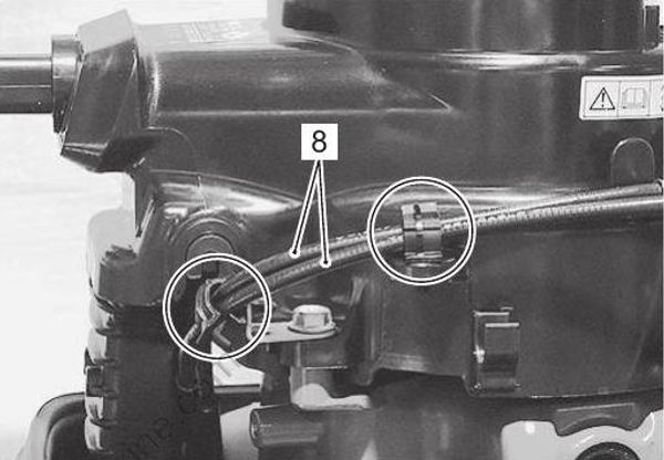
7) Remove the throttle cables (8) from the two clamps.
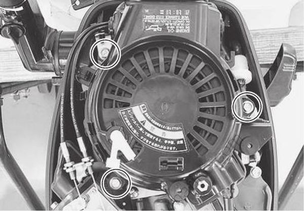
8) Remove the three bolts securing the recoil starter, then remove the recoil starter.
Installation
Installation is in the reverse order of removal with special attention to the following.
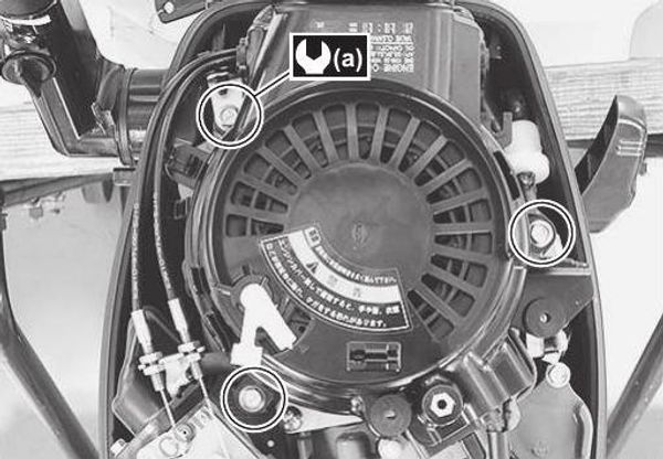
- Install the recoil starter, then tighten the bolts to the specified torque.
Tightening torque
Recoil starter mounting bolt (a): 10 N-m (1.0 kgf- m, 7.2 lbf-ft)
- Check to ensure that all removed parts are back in place.
- Check the neutral start interlock function.
Refer to “NSI Cable Installation and Adjustment” (Page 1J-9).
Recoil Starter Disassembly and Assembly
Failure to take proper precautions when servicing the recoil starter can cause personal injury.
Wear safety glasses and hand protection when winding or unwinding this component.
Disassembly
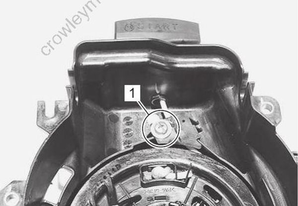
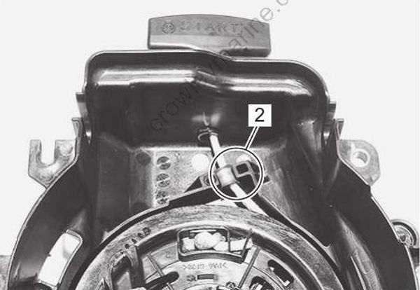
1) Remove the screw securing the rope guide (1), then remove the guide and the spacer (2) from the recoil starter case.
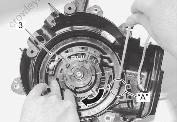
2) Pull the rope out of recoil case and guide the rope into notch “A” in the reel (3), then turn the reel clockwise to release the coiled tension in the recoil spring.
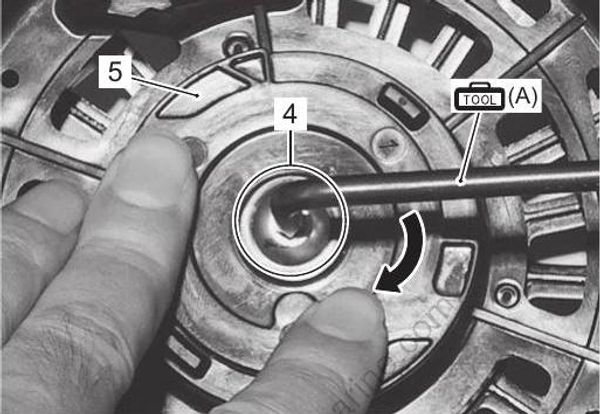
3) Using special tool, remove the center screw (4) and the friction plate (5).
Special tool (A): 09930–11950 (Torx® wrench (T25H))
The center screw is left-hand thread.
4) Remove the ratchets (6) and the friction spring (7).
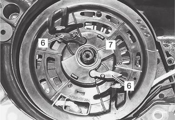
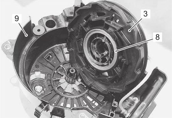
5) Slowly remove the reel (3) with the recoil spring (8) from the recoil case (9).
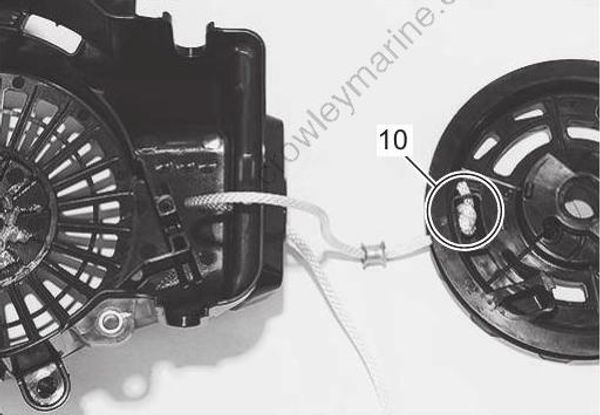
6) Remove the recoil rope (10) from the reel.
Do not remove the recoil spring unless replacement is necessary.
It should be visually inspected in its assembled position.
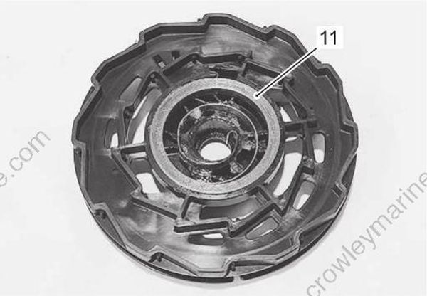
7) Remove the recoil spring (11).
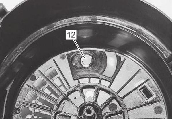
8) Remove the E-ring (12).
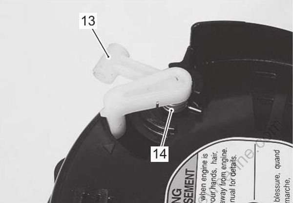
9) Remove the reel stopper (13) and the spring (14).
Assembly
Reassembly is in the reverse order of disassembly with special attention to the following reassembling step.
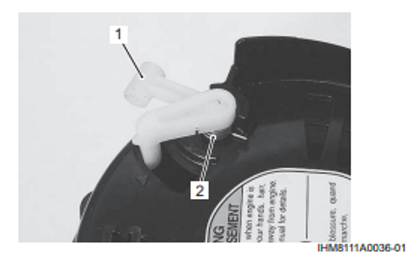
- Install the reel stopper (1) and the spring (2) as shown in the figure.
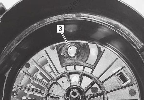
- Install the E-ring (3).
- Secure the outer end “A” of the recoil spring (4) on groove “B” in the reel (5) and wind spring inward towards center of case in a counterclockwise direction.
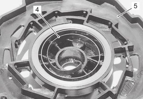
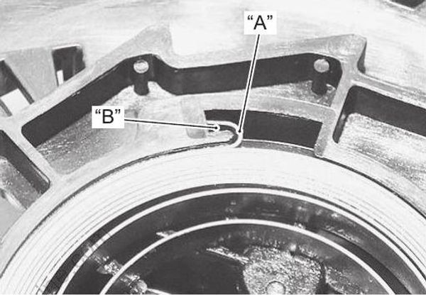
- Install the recoil rope (6).
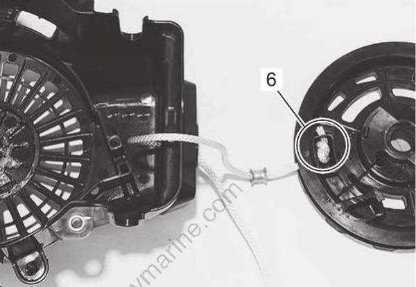
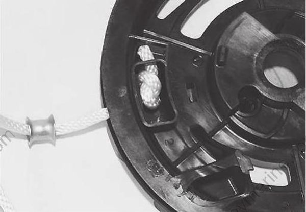
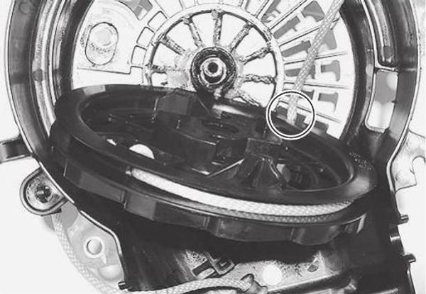
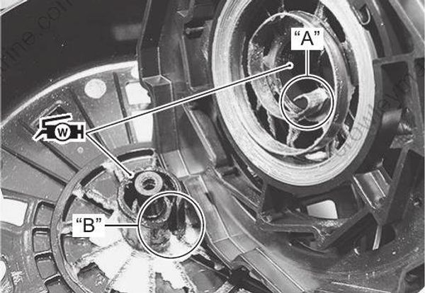
- Install the reel and the recoil spring to the recoil case aligning the inner end of the spring “A” with the boss cutaway “B” on the recoil case.
• Apply grease to the reel as shown in the figure.
• To rotate the reel, adjust the position of the reel stopper by hand.
: Grease 99000–25350 (SUZUKI Water Resistant Grease EP2 (250 g))
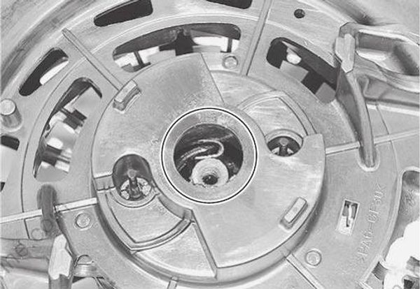
- Install the ratchets (7) and the friction spring (8).
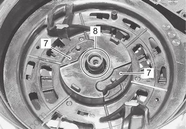
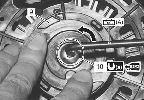
- Install the friction plate (9) and secure it with screw (10) using special tool.
Apply thread lock 1342H to screw before threading.
Tightening torque
Center screw (a): 3 N-m (0.3 kgf-m, 2.5 lbf-ft)
Special tool
(A): 09930–11950 (Torx® wrench (T25H))
: Thread lock cement 99000–32160 (SUZUKI Thread Lock 1342H (50g))
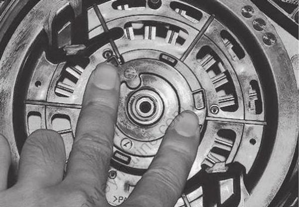
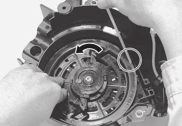
- After assembling, guide the rope onto the reel and rotate the reel counterclockwise in approximately 5 turns until the spring is tensioned.
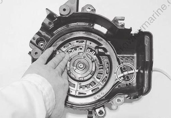
- Install the rope guide to the recoil case.
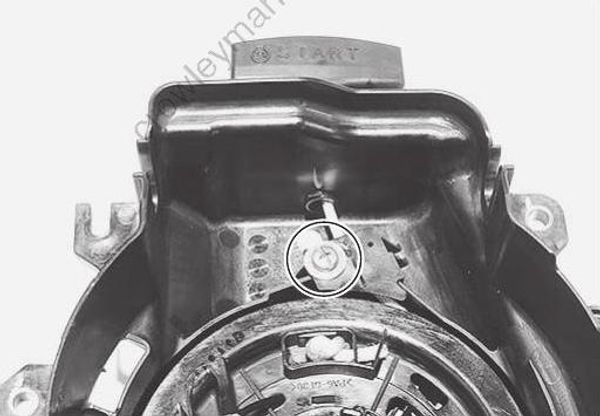
Recoil Starter Components Cleaning and Inspection
If any parts is worn excessively, cracked, defective or damaged in any way, it must be replaced.
- Wash metal components in cleaning solvent and dry with compressed air before inspection.
- Inspect the reel, recoil case.
If any cracks or damage is found on them, replace it. - Inspect the recoil rope.
If the recoil rope is worn or damaged, replace it.
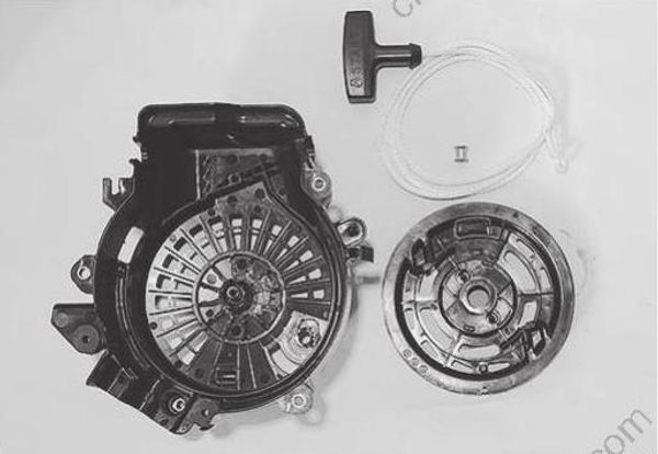
- Inspect the recoil spring.
If there is any cracks, deformation or excessive curve on the recoil spring, replace it. - Inspect the ratchet (pawl) and the friction spring. If there is any defect such as excessive wear or damage, replace it.
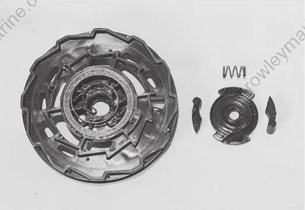
- Inspect the reel stopper.
If any cracks or damage is found on them, replace it.
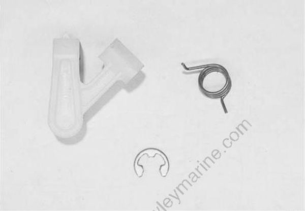
NSI Cable Installation and Adjustment
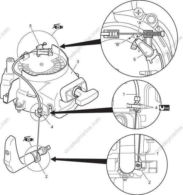
1) Install the NSI cable (1) to the reel stopper (5) as shown in the figure.
2) Shift into “Forward” position.
3) Install the NSI cable (1) to clutch notch plate (2).
4) Shift into “Neutral” position.
5) Install the NSI cable (1) to recoil starter case (3), then tighten the lock nuts (4) temporarily.
6) Turn the lock nut to align the arrow mark “A” with the arrow mark “B”.
7) Pull the recoil starter grip and make sure that the starter does not work when the shift lever is in “Forward” and “Reverse” position.
8) Tighten the lock nut securely.
Tightening torque
Lock nut (a): 4 N-m (0.4 kgf-m, 3.0 lbf-ft)
9) Apply water resistant grease to the inner cable, the clutch notch plate and the reel stopper.
: Grease 99000–25350 (SUZUKI Water Resistant Grease EP2 (250 g))
If the NSI cable is removed or left without correct adjustment, there is a high risk of losing one’s balance and/or being thrown overboard if the motor starts in gear.
Do not operate the motor when the NSI cable is detached or the adjustment is not correctly done.
