Precautions
Precautions on Fuel System Service
Service operation of any type performed on the fuel system involves a risk of fire and injury if proper precautions are not taken.
Be sure to take the following precautions when working around gasoline or servicing the fuel system.
• Disconnect battery cables except when battery power is required for servicing / inspection.
• Keep the working area well ventilated and away from open flame (such as gas heater) or sparks.
• Do not smoke or allow anyone else to smoke near the working areas. Post a “NO SMOKING” sign.
• Keep a fully charged CO2 fire extinguisher readily available for use.
• Always use appropriate safety equipment and wear safety glasses when working around a pressurized fuel system.
• To avoid potential fire hazards, do not allow fuel to spill on hot engine parts or on operating electrical components.
• Wipe up fuel spills immediately.
• When disconnecting a fitting on the fuel line, cover the fitting with a shop cloth to soak up the small amount of fuel that may flow out from the disconnected fuel line. Put the used cloth in an approved container.
• Since fuel hose connections vary with the pipe type, connect and clamp each hose using the correct method for each specific connection.
After connecting a hose, check that there is no twist or kink in the hose.
• When installing hose clamps, position tabs to avoid contact with other parts.
• Be sure hoses do not contact rods, levers or other components with engine either operating or at rest.
General Description
Fuel System Description
The main components of the fuel system are fuel tank, fuel filter, fuel pump, carburetor and fuel feed line.
A mechanical diaphragm type fuel pump on the motor draws fuel from the fuel tank through the fuel filter and supply it to the carburetor.
The flow of the fuel is shown in the figure.
Before the engine is started:
When the air vent on the fuel tank cap and the fuel cock are open, fuel is supplied to the carburetor through the fuel tank, fuel cock and check valve.
After the engine is started:
Fuel is supplied to the carburetor through the fuel tank and fuel cock, as well as the fuel filter and fuel pump.

1.Fuel tank cap (with air vent)
2.Fuel tank
3.Fuel cock
4.Check valve (for US market)
5.Check valve
6.Fuel filter
7.Fuel pump
8.Carburetor
9.Fuel connector (except for DF4A)
“A”:The flow of the fuel (Before the engine is started.)
“B”:The flow of the fuel (After the engine is started.)
Principles of Carburetor Operation Description
Float system
Fuel enter the carburetor from the fuel pump through the fuel inlet and float controlled needle valve into the float chamber.
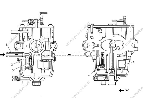
1.Float
2.Float valve seat
3.Float valve
4.Float Pin
5.Fuel inlet joint
“A”:Fuel
Idling / Trolling Speed
After passing through the pilot jet (1), fuel mixes with air that is supplied from the pilot air jet (2).
This mixture then passes through the pilot screw (9) seating area and is jetted both from the pilot outlet (3) and bypass port #1 (5).
No mixture will be jetted either from the bypass port #2 (6) or from those located upstream but these ports serve as air passage.
As the pilot screw (9) is turned clockwise (screwed in), the mixture (A/F) will become leaner. As the screw is turned counterclockwise (screwed out), the mixture will become richer.
The throttle stop screw is designed to adjust the idling/trolling speed. When the stop screw is turned clockwise (screwed in), the speed raises and when turned counterclockwise (screwed out), the speed lowers.

1.Pilot jet
2.Pilot air jet
3.Pilot outlet
4.Bypass port
5.Bypass port #1
6.Bypass port #2
7.Bypass port #3
8.Bypass port #4
9.Pilot screw
“A”:AIR
“B”:FUEL + AIR (MIXTURE)
“C”:FUEL
Low-Mid Speed
As the throttle valve (10) is opened gradually, air flowing through the throttle bore increases in proportion to the valve opening angle. At this time, because fuel mixture jets from the bypass port #2 (6) and those upstream successively, the mixture ratio (A/F) is maintained to be optimum, thereby the engine speed being raised smoothly.

1.Pilot jet
2.Pilot air jet
3.Pilot outlet
4.Bypass port
5.Bypass port #1
6.Bypass port #2
7.Bypass port #3
8.Bypass port #4
9.Pilot screw
10.Throttle valve
“A”:AIR
“B”:FUEL + AIR (MIXTURE)
“C”:FUEL
Mid-High Speed
When the throttle valve opens further and engine speed rises, fuel passes through the main jet (1) and enters the main nozzle (3), in which it is mixed with air supplied from the main air jet (2) before sprayed into the main bore.

1.Main jet
2.Main air jet
3.Main nozzle
“A”:AIR
“B”:FUEL + AIR (MIXTURE)
“C”:FUEL
Diagnostic Information and Procedures
Fuel System Diagnosis
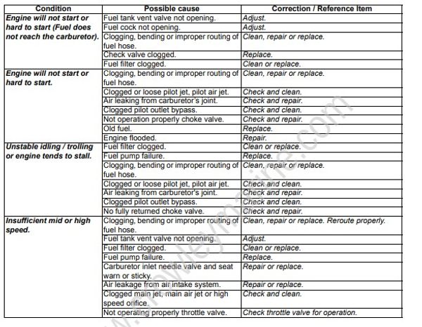
Service Instructions
Fuel Line Removal and Installation
Pay special attention to the following points when removing or installing fuel hoses.
Gasoline is a flammable material that can cause fire hazard or burns.
Before starting the following procedure, be sure to observe “Precautions on Fuel System Service” in order to reduce the risk or fire and personal injury.
- Spilled gasoline should be wiped off immediately.
- Perform the following checks to ensure proper and safe operation of the repaired unit.
– Check fuel hose routing.
Refer to “Fuel Hose Routing” in Section 4B (Page 4B-2).
– Check for fuel leakage.
No fuel leakage is evident during final test running.
Fuel Line Inspection
Inspection of Fuel Hose Connections
Note that the fuel hose connection varies with each type of pipe. Be sure to connect and clamp each hose correctly by referring to the figure.
- For type “A” (short barbed end) pipe, the hose must completely cover pipe.
Type “A”
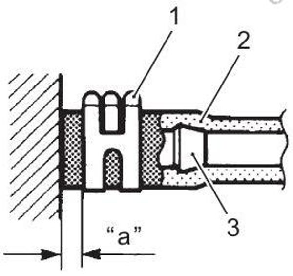
1.Clamp (Clip)
2.Hose
3.Joint pipe
“a” : 3 - 7 mm (0.1 - 0.3 in)
- For type “B” (bent end) pipe, hose must cover the straight part of pipe by 20 - 30 mm (0.8 - 1.2 in.).
Type “B”
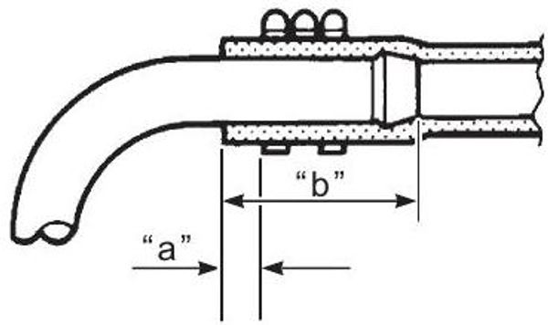
“a” : 3 - 7 mm (0.1 - 0.3 in)
“b” : 20 - 30 mm (0.8 - 1.2 in)
- For type “C” pipe, hose must fit up against the flanged part of pipe.
Type “C”
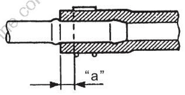
“a” : 3 - 7 mm (0.1 - 0.3 in)
- For type “D” pipe, the hose must cover the pipe by 20 - 30 mm (0.8 - 1.2 in.).
Type “D”
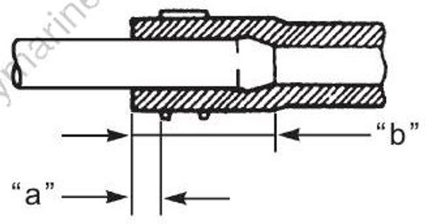
“a” : 3 - 7 mm (0.1 - 0.3 in)
“b” : 20 - 30 mm (0.8 - 1.2 in)
Carburetor Components
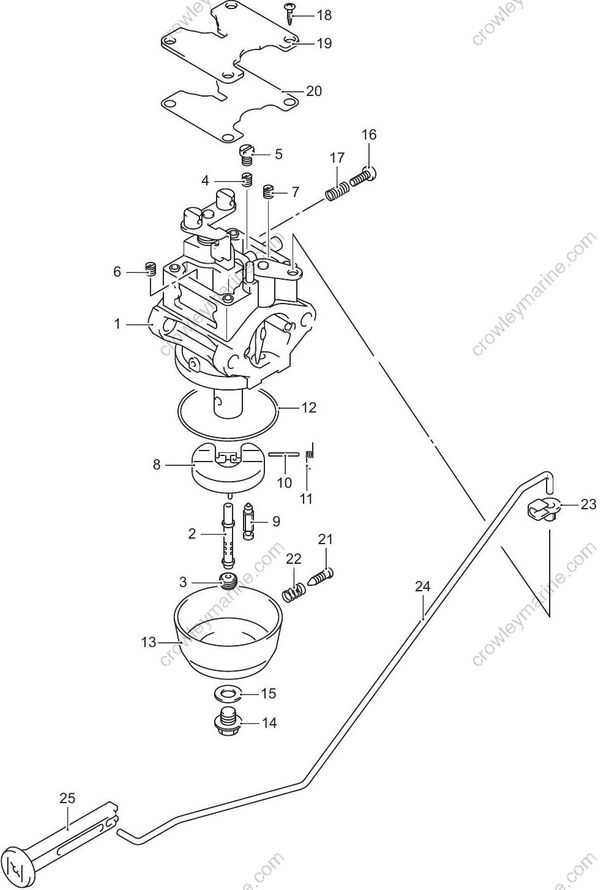
1.Carburetor body
2.Main nozzle
3.Main jet
4.Pilot jet
5.Pilot jet cap
6.Main air jet
7.Pilot air jet
8.Float
9.Needle valve
10.Float pin
11.Spring
12.Float chamber gasket
13.Float chamber
14.Bolt
15.Gasket
16.Throttle stop screw
17.Spring
18.Screw
19.Plate
20.Gasket
21.Drain screw
22.Spring
23.Choke rod connector
24.Choke rod
25.Choke knob
Carburetor Removal and Installation
Removal
1) Remove the fuel tank.
Refer to “Fuel Tank Removal and Installation” (Page 1G-19).
2) Detach the choke rod (1) from the carburetor and the choke knob.
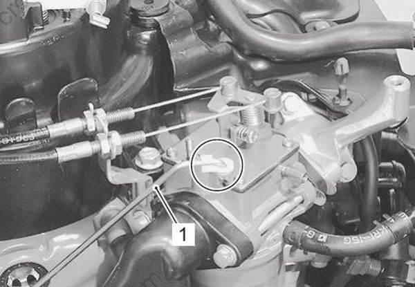
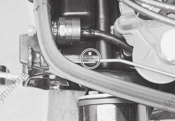
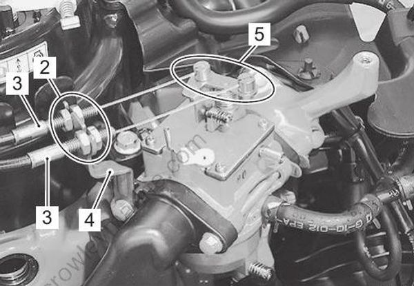
3) Loosen the throttle control cable lock nuts (2), then remove the throttle control cables (3) from the throttle control cable bracket (4) and the linkages (5).
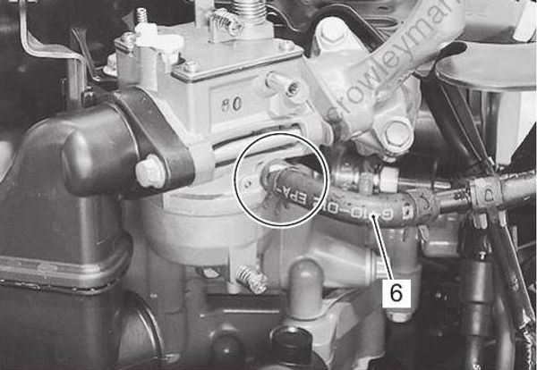
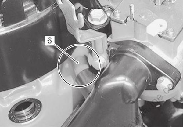
4) Detach the fuel inlet hose (6) from the carburetor.
5) Remove the two bolts (7) securing the carburetor and silencer.
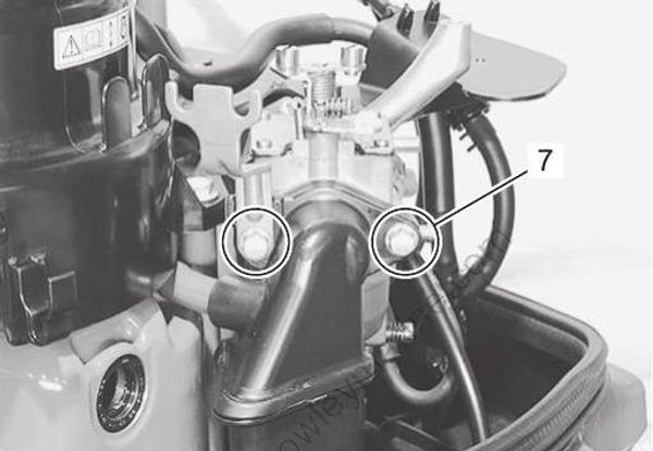
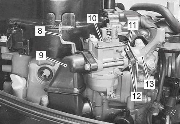
6) Remove the throttle control cable bracket (8), silencer (9), carburetor (10), insulator (11) and gaskets (12) from the intake manifold (13).
Installation
Installation is in the reverse order of removal with special attention to the following steps.
Air leakage will induce a lean air / fuel mix which will result in severe engine damage.
Do not reuse gasket once removed. Always use a new gasket.
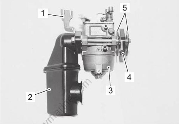
- Assemble the throttle control cable bracket (1), silencer (2), carburetor (3), insulator (4) and gaskets (5).
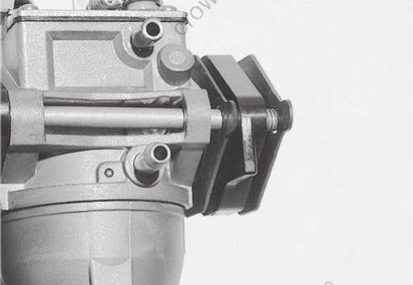
The projection of insulator and gaskets must be faced as shown in the figure.
- Install the carburetor/silencer assembly and insert the breather hose (6) to the silencer, then tighten the carburetor mounting bolts, pre-coated with thread lock, to the specified torque.
Tightening torque
Carburetor mounting bolt (a): 10 N·m (1.0 kgf⋅m, 7.2 lbf⋅ft)
: Thread lock cement 99000–32160 (SUZUKI Thread Lock 1342H (50g))

- Install the throttle control cables to the throttle control cable bracket and the linkages, and adjust the throttle control cables.
Refer to “Throttle Control Cable Installation and Adjustment” in Section 2A (Page 2A-6).

• Perform the following final assembly checks to ensure proper and safe operation.
– All parts removed have been returned to their original positions.
– Hose routing matches service manual illustration. Refer to “Fuel Hose Routing” in Section 4B (Page 4B-2).
– No fuel leakage is evident during final test running.
Carburetor Disassembly and Assembly
Disassembly
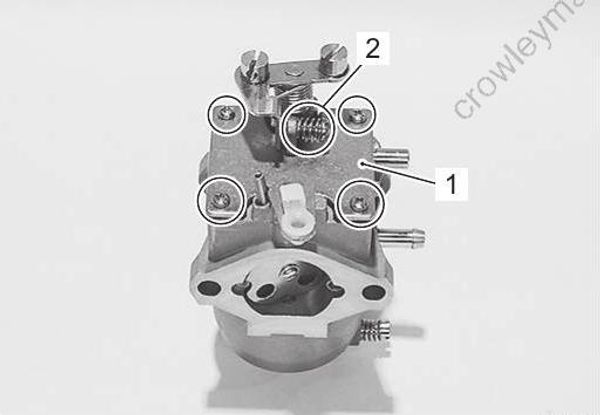
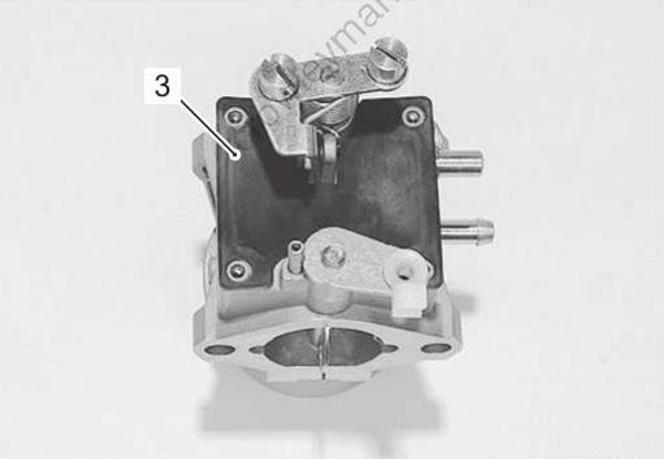
1) Remove the four screws securing the top cover (1) and the throttle stop screw (2),then remove the cover and rubber gasket (3).
Do not remove the cover “A” and adjust pilot screw “B”.
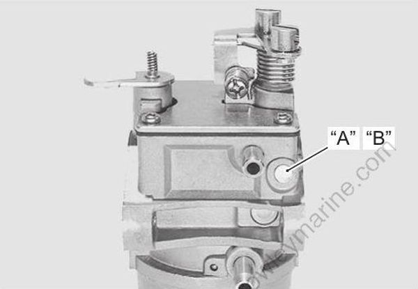
“A”: Cover
“B”: Pilot screw
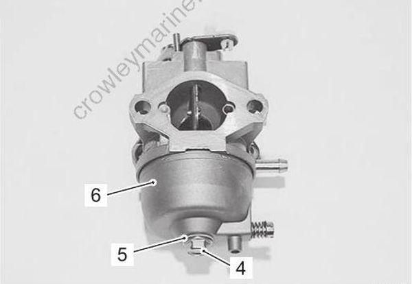
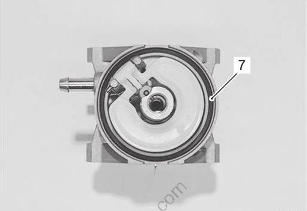
2) Remove the float chamber bolt (4) and the gasket (5), then remove the float chamber (6) and the rubber gasket (7).
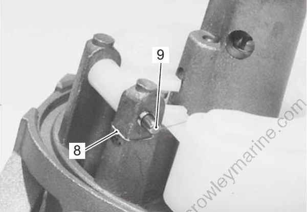
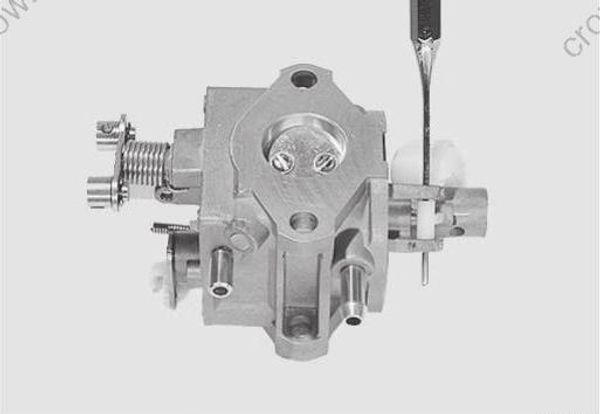
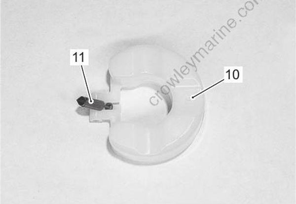
3) Remove the spring (8) and the float pin (9).
Account for the float (10) and the needle valve (11).
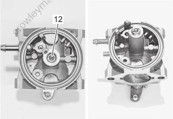
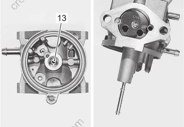
4) Remove the main jet (12) and main nozzle (13).
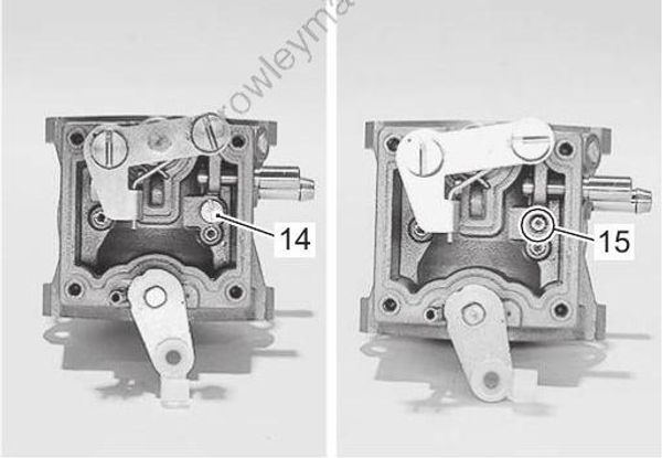
5) Remove the pilot jet cap (14) and pilot jet (15).
Reassembly
Reassembly is in the reverse order of disassembly with special attention to the following steps.
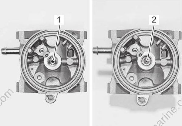
Jet
Install the main nozzle (1) and main jet (2) into carburetor tower.
Install the pilot jet (3) and pilot jet cap (4).

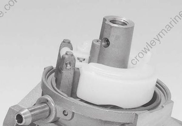
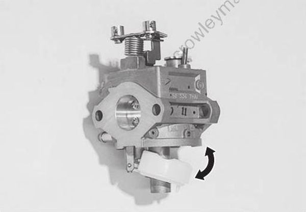
Float
Install the float (with needle valve), spring and float pin.
After installing float, inspect for smooth movement of float.
Float Chamber
Previously used gasket may leak fuel, resulting in engine damage.
Do not reuse gasket. Always replace with new part.
• Install a new rubber gasket (1) to the carburetor body.
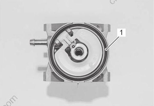
• Install the float chamber (2), and install a new gasket (3) and the float chamber bolt (4), then tighten the bolt securely.
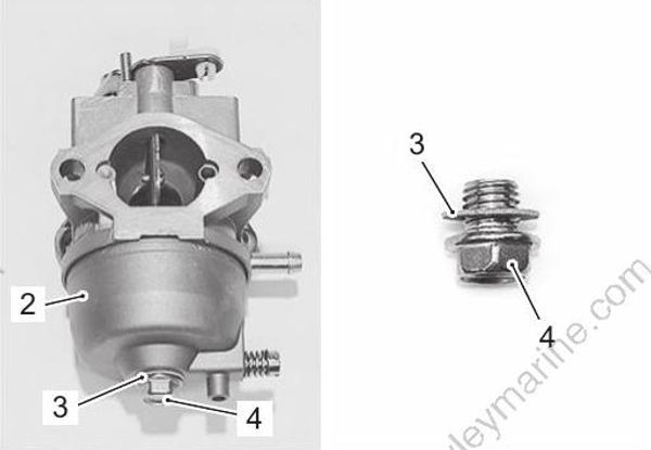
Carburetor Components Cleaning and Inspection
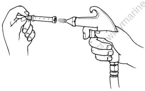
Clean thoroughly with cleaning solvent and compressed air before inspection.
Failure to following proper precautions during use of the compressed air may cause severe personal injury.
Wear safety glasses when using compressed air.
Cleaning solvent will severely damage rubber, plastic and non-metallic parts, and will cause them to deteriorate.
Do not let cleaning solvent come into contact with rubber, plastic and non-metallic parts.
Wire or small drill bits must not be used to clean carburetor orifices and jet.
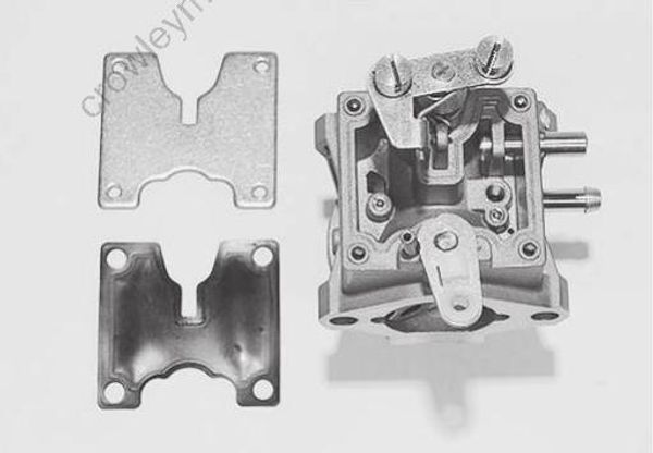
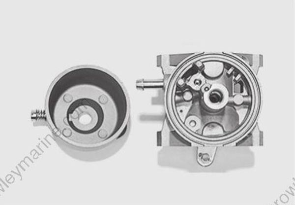
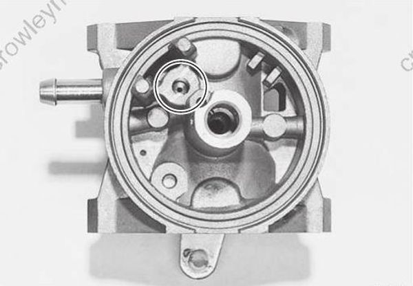
Carburetor Body and Top Cover
- Inspect the carburetor body and top cover. If cracks or other damage are found on any component, replace it.
- Clean the carburetor body so that there is no obstruction.
- Inspect the needle valve seat. Replace carburetor body if wear, damage, or other abnormal condition.
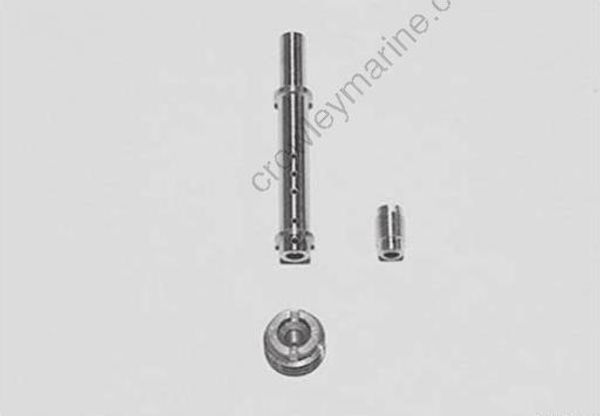
Jet and Nozzle
- Inspect the jet and nozzle. If cracks or other damage are found on the jet and nozzle, replace them.
- Clean the jet and nozzle thoroughly so that there is no obstruction.
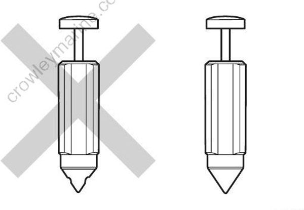
Needle Valve
Inspect the needle valve assembly. If broken tips or wear are found on the needle valve, replace it.
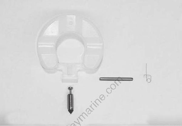
Float
Inspect the float.
If cracks or other damage are found on the float, replace it.
Fuel Pump Removal and Installation
Removal
1) Disconnect the inlet hose (1) and outlet hose (2) from the fuel pump (3).

2) Remove the two bolts (4) securing the fuel pump, then remove the fuel pump and O-ring (5).

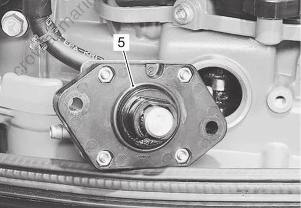
Installation
Installation is in the reverse order of removal with special attention to the following steps.
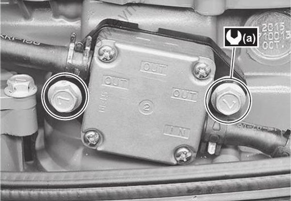
- Install the fuel pump to the cylinder block, then tighten the bolts to the specified torque.
Do not reuse O-ring once removed. Always use a new O-ring.
Tightening torque
Fuel pump mounting bolt (a): 7 N·m (0.7 kgf⋅m, 5.0 lbf⋅ft)
- Perform the following final assembly checks to ensure proper and safe operation.
– All parts removed have been returned to their original positions.
– Hose routing matches service manual illustration. Refer to “Fuel Hose Routing” in Section 4B (Page 4B-2).
– No fuel leakage is evident during final test running.
Fuel Pump Disassembly and Assembly
Disassembly
1) Remove the fuel pump.
Refer to “Fuel Pump Removal and Installation” (Page 1G-16).
2) Remove the four screws (1) and nuts (2) securing the outer plate (3), and remove in sequence the outer plate (3), the diaphragm (4) and the valve body (5).


3) Turn the piston (6) and the diaphragm (7) together until the pin (8) comes out through cutaway of pump body (9).
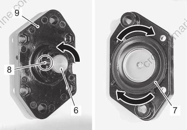
4) Remove the pin (8), piston (6), piston spring (10), diaphragm (7) and diaphragm spring (11).
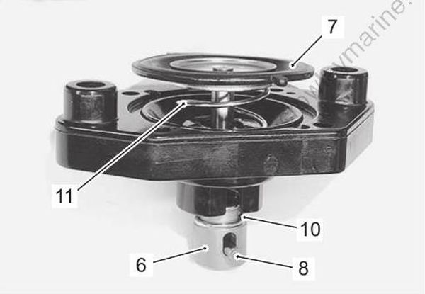
Assembly
Assembly is in the reverse order of disassembly with special attention to the following steps.
Previously used diaphragms may leak fuel, resulting in engine damage.
Do not reuse diaphragms. Always replace with new part.
- After connecting the diaphragm rod to the piston (1) with the pin (2), align the two diaphragm projections to the pump body hollows by turning the piston and the diaphragm (3) together in order to prevent the pin from coming out through the cutaway of the pump body (4).

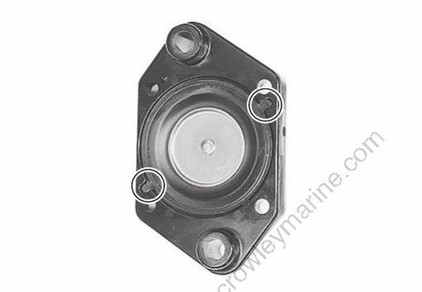
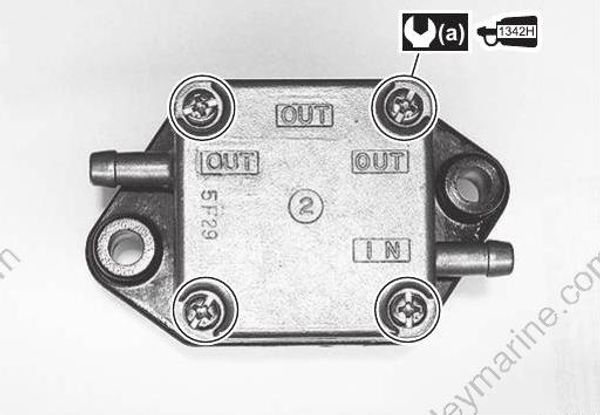
- Tighten the four screws, pre-coated with thread lock, to the specified torque.
Tightening torque
Outer plate screw (a): 2 N·m (0.2 kgf⋅m, 1.5 lbf⋅ft)
: Thread lock cement 99000–32160 (SUZUKI Thread Lock 1342H (50g))
Fuel Pump Components Inspection
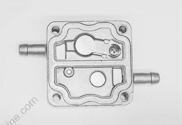
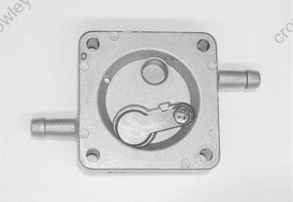
Valve Body
Inspect the check valves. If tears, distortion or damage is found, replace the fuel pump assembly.
Pump Body
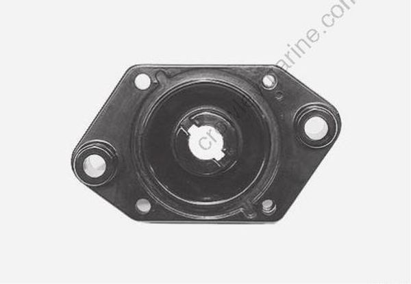
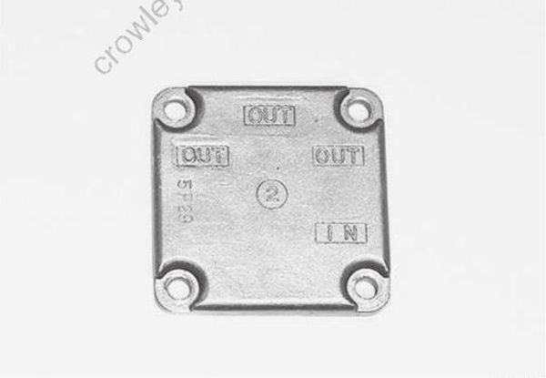
Inspect the pump body and outer plate.
If cracks, nicks, distortion or damage is found, replace the fuel pump assembly.
Fuel Line Check Valve Inspection
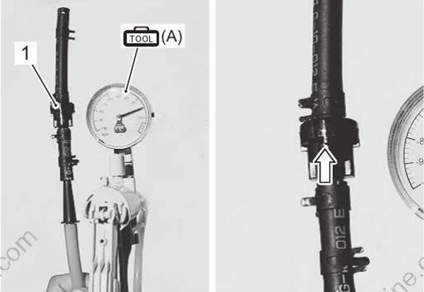
1) Inspect the check valve. If there are any cracks or deterioration, replace the check valve.
2) Connect a vacuum pump gauge (with hose) to the check valve (1) as shown in the figure and apply negative pressure to the check valve.
If the gauge shows the pressure slowly returning to zero, the check valve is correct.
If the gauge shows the pressure immediately returning to zero, replace the check valve.
Special tool
(A): 09917–47011 (Vacuum pump gauge)
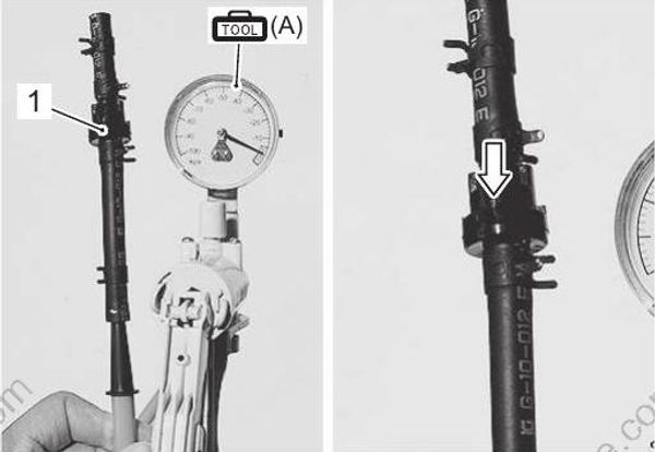
3) Connect a vacuum pump gauge (with hose) to the check valve (1) as shown in the figure and apply negative pressure to the check valve. If the gauge shows the pressure immediately returning to zero, the check valve is correct. If the gauge does not show the pressure returning immediately to zero, replace the check valve.
Fuel Tank Removal and Installation
Removal
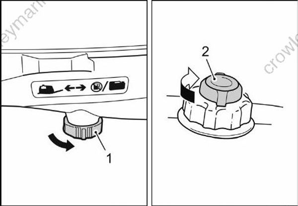
1) Turn the fuel cock lever (1) to the right (off position) and tighten the air vent screw on the fuel filler cap (2).
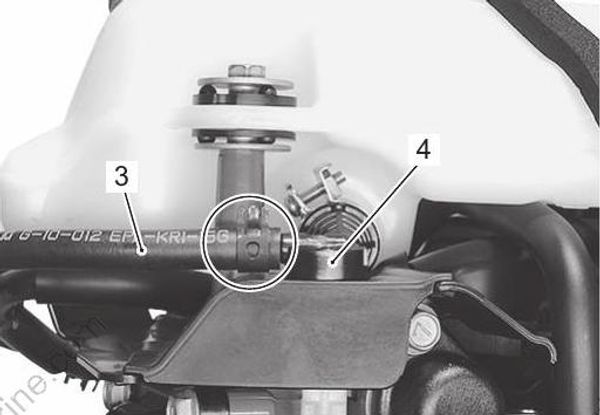
2) Remove the fuel hose (3) from the fuel cock (4) and immediately plug the fuel hose in order to avoid fuel flow from the hose.
3) Remove the three bolts (5) securing the fuel tank (6), then remove the fuel tank.

Installation
Installation is in the reverse order of removal with special attention to the following steps.
- Before installing the fuel tank, drain all fuel from the tank.
- Install the fuel tank, then insert the fuel cock lever (1) to the fuel cock shaft (2).
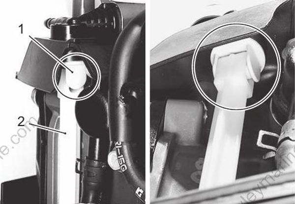
- Tighten the fuel tank mounting bolts to the specified torque.
Tightening torque
Fuel tank mounting bolt (a): 10 N·m (1.0 kgf⋅m, 7.2 lbf⋅ft)

- Perform the following final assembly checks to ensure proper and safe operation.
– All parts removed have been returned to their original positions.
– Fuel hose routing matches service manual illustration.
Refer to “Fuel Hose Routing” in Section 4B (Page 4B-2).
– No fuel leakage is evident during final test running.
Fuel Tank Components
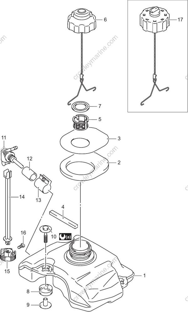
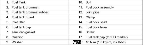
Fuel Tank Disassembly and Reassembly
Disassembly
1) Loosen the screw (1) and remove the fuel cock (2)
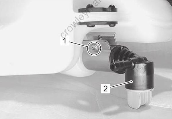
2) Drain all fuel from the tank.
3) Loosen and detach the fuel tank cap.
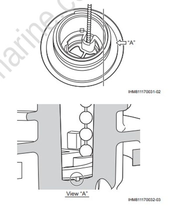
4) Rotate the fuel inlet filter (3) until the gap of the filter and projection of the fuel tank are aligned as shown in the figure.
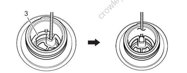
5) Remove the fuel inlet filter and the fuel tank cap from the fuel tank.
Reassembly
Reassembly is in the reverse order of disassembly with special attention to the following steps.
- Install the fuel cock to the fuel tank as shown in the figure.

“a”: 30 ± 10°
“b”: 3.0 mm (0.118 in.)
- Install the fuel inlet filter (1) to the fuel tank, then align the gap of the filter and projection of the fuel tank as shown in the figure.
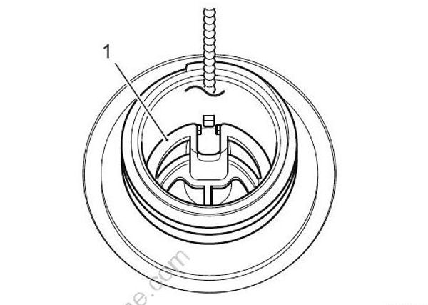
• To install the fuel inlet filter onto the fuel tank, rotate the fuel inlet filter until the projection fits into the notch as shown in the figure.
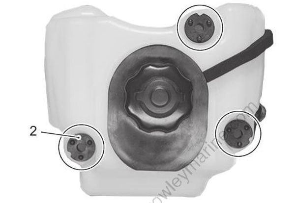
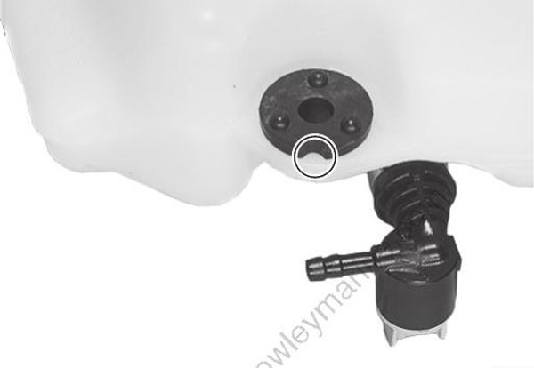
- Install the three fuel tank cushions (2) to the fuel tank as shown in the figure.
Fuel Tank Components Inspection
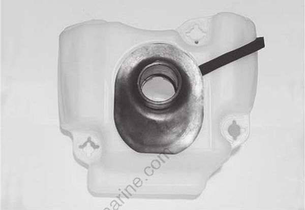
Fuel Tank Body
Inspect the fuel tank. If crack, leakage or deterioration is found, replace the tank.
If water or other contamination is found, drain and clean the tank.
Fuel Tank Cap
Check that the fuel tank vent opens and relieves internal tank pressure properly.
If vent is suspect, replace the tank cap.
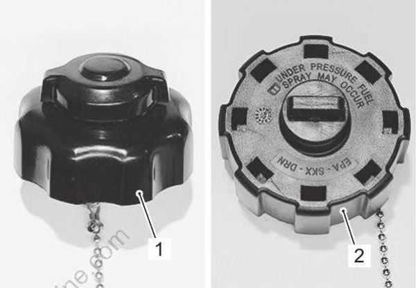
- Except for US market
- For US Market
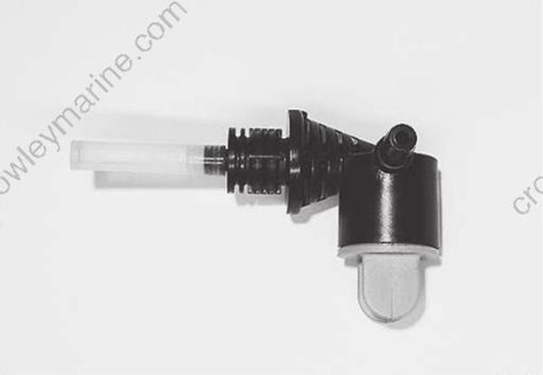
Fuel Cock
- Inspect the fuel cock. If leakage, deterioration or other damage is found, replace the cock.
- Inspect the fuel filter for dirt, clog. Clean the filter if necessary.
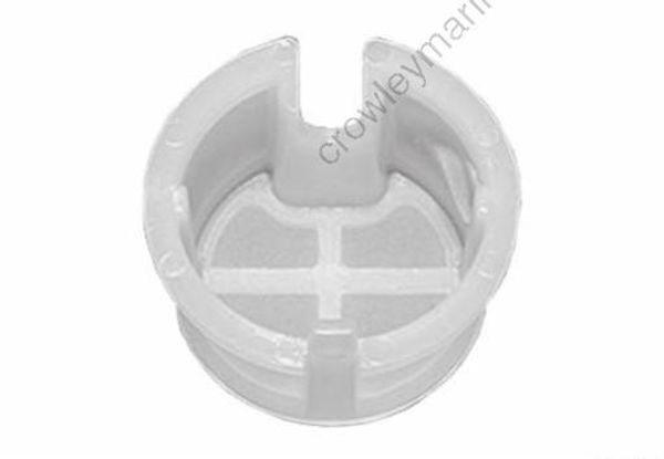
Fuel Inlet Filter
Inspect the fuel inlet filter. Replace the filter if cracked, damaged or other abnormal conditions.
If clog or obstruction, clean the fuel inlet filter.
Fuel Tank Plate Removal and Installation
Removal
1) Remove the fuel tank.
Refer to “Fuel Tank Removal and Installation” (Page 1G-19).
2) Detach the fuel hose from the fuel pump outlet.
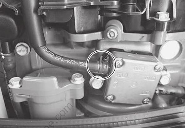
3) Remove the fuel hoses from the clamps.
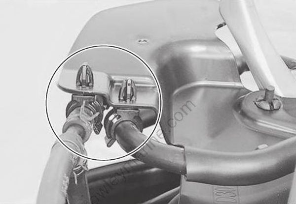
4) Remove the high-tension cord clamp (1) from the fuel tank plate (2).
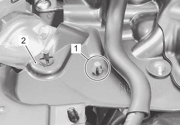
5) Remove the fuel tank plate (2) and the fuel tank plate cover (3) from the cylinder head and the recoil starter grommet.
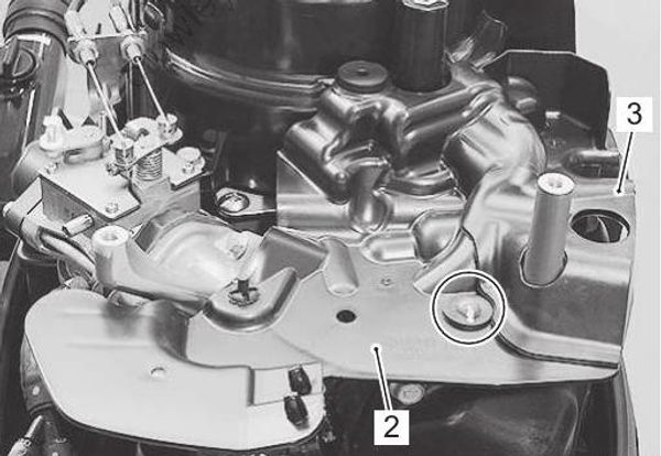
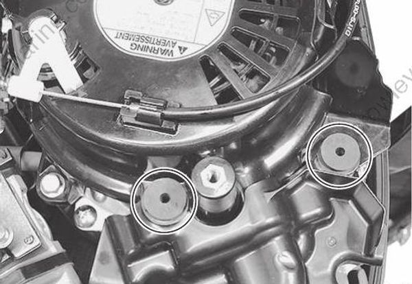
Installation
Installation is in the reverse order of removal with special attention to the following steps.
- Check to ensure that all removed parts are back in place.
- Check fuel hose and wire routing.
Refer to “Fuel Hose Routing” in Section 4B (Page 4B-2) and “Wiring Harness Routing Diagram” in Section 4A (Page 4A-4).
- No fuel leakage is evident during final test running.
Fuel Tank Construction (Optional Part
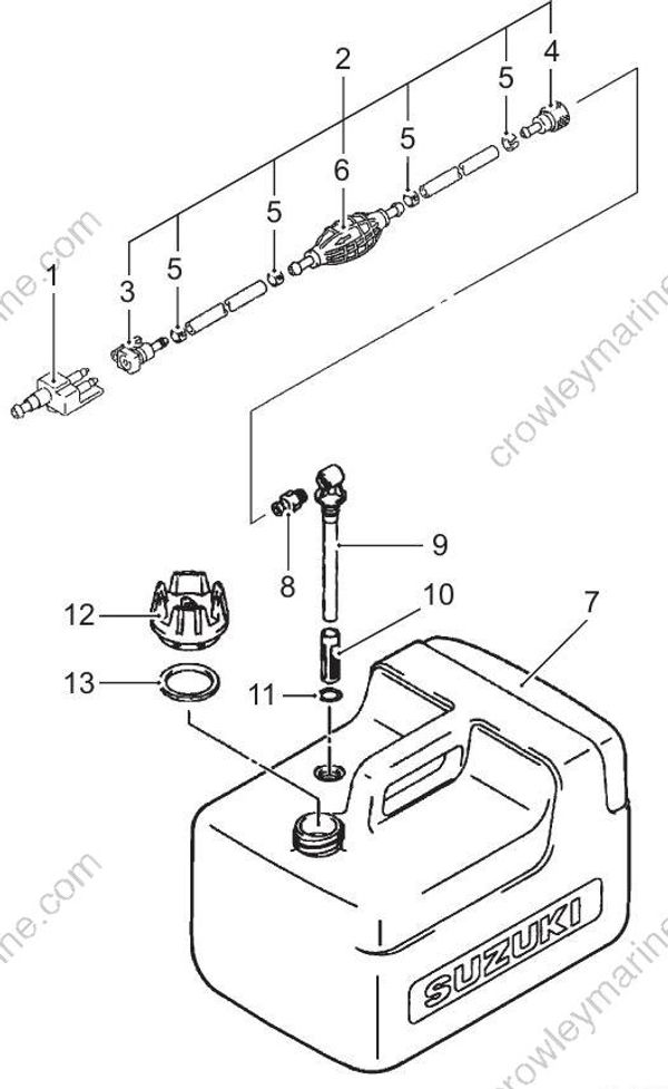
1.Fuel plug
2.Fuel hose assembly
3.Socket
4.Socket
5.Clip
6.Primer bulb
7.Fuel tank body
8.Fuel connector plug
9.Outlet
10.Outlet filter
11.O-ring
12.Fuel tank cap
13.Fuel tank cap gasket
Fuel Tank Disassembly and Reassembly
When disassembling or reassembling the fuel tank, refer to “Fuel Tank Construction (Optional Part)” (Page 1G-25).
Fuel Tank Components Inspection
Fuel Connector
Inspect the fuel connector and connector plug. If leakage, deterioration or other damage is found, replace the connector and/or plug.

- Connector
- Connector plug
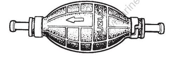
Fuel Primer Bulb
Inspect the fuel primer bulb.
If crack, leakage or deterioration is found, replace the bulb.
If the check valve function is defective, replace the bulb.
Fuel Hose
Inspect the fuel hoses. If cut, crack, leakage, abrasion, tear or deterioration is found, replace the hoses.
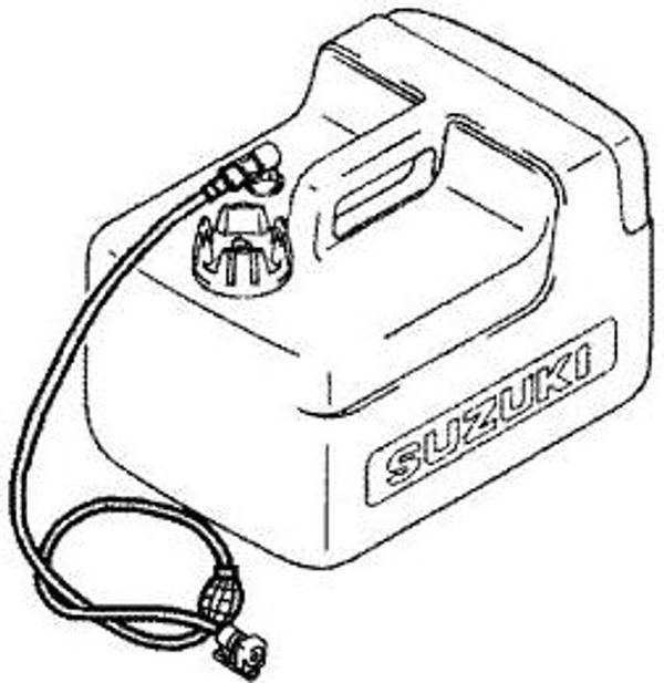
Fuel Tank Body
Inspect the fuel tank. If crack, leakage or deterioration is found, replace the tank.
If water or other contamination is found, drain and clean the tank.
Fuel Tank Cap
Check that the fuel tank vent opens and relieves internal tank pressure properly.
If vent is suspect, replace the tank cap.