

Step 1: INSPECTION
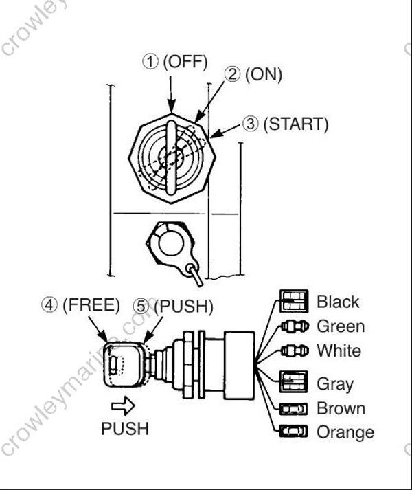
IGNITION SWITCH
09930-99320 : Digital tester
Tester range : (Continuity)
- Disconnect the ignition switch from remo-con box wiring harness.
- Check continuity between wiring leads at the key positions shown in the chart.
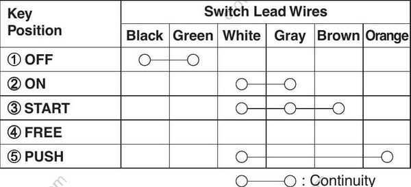
If out of specification, replace ignition switch.
Step 2: NEUTRAL SWITCH
Check for continuity / infinity of the neutral switch.
09930-99320 : Digital tester
Tester range : (Continuity)
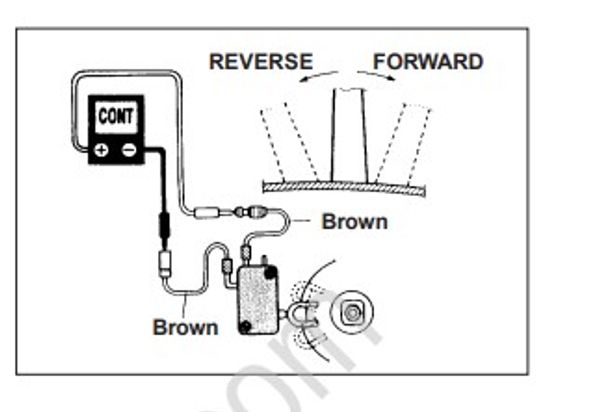
Neutral switch in remo-con box
- Disconnect neutral switch lead wire from ignition switch and remo-con box wiring lead.
- Check continuity / infinity between switch brown wire leads while operating remo-con handle.
| Shift position | Tester indicates |
|---|---|
| Neutral | Continuity |
| Forward | Infinity |
| Reverse | Infinity |
If out of specification, replace neutral switch.
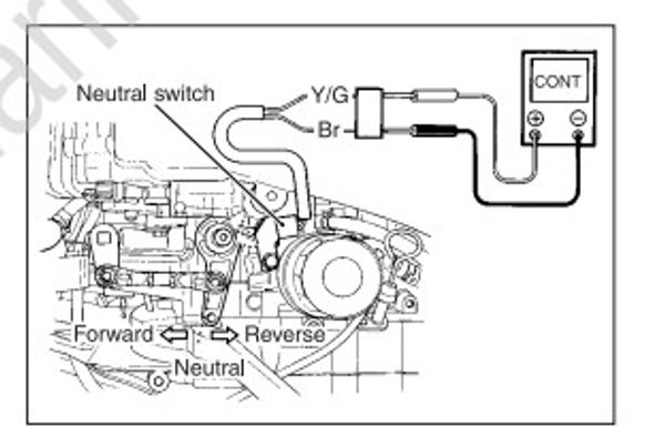
Neutral switch on cylinder block
- Disconnect neutral switch lead wires.
- Check continuity / infinity between Yellow / Green and Brown lead wires while operating remo-con handle.
| Shift position | Tester indicates |
|---|---|
| Neutral | Continuity |
| Forward | Infinity |
| Reverse | Infinity |
If out of specification, replace neutral switch.
After installing neutral switch, check for proper correct function by operating remo-con handle.
Step 3: STARTER MOTOR RELAY
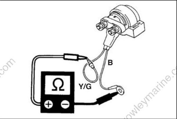
Two methods can be used to test starter motor relay.
09930-99320 : Digital tester
Method 1
- Disconnect all cables / lead wires from starter motor relay.
- Measure resistance between relay wiring leads.
Tester range : Ω (Resistance)
| Tester probe connection | |
|---|---|
| Red (+) | Black (-) |
| Yellow / Green | Black |
Starter motor relay solenoid coil resistance : 3.5 – 5.1 Ω
If measurement exceeds specification, replace starter motor relay.
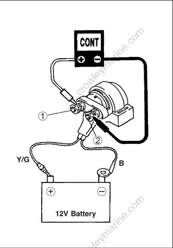
Method 2
Connect the wiring leads of the relay to battery (12V) and check relay operation.
Tester range : (Continuity)
- Disconnect all cables / wires from starter motor relay.
- Connect Yellow /Green wire to positive (+) terminal, and Black wire to negative (-) terminal of battery.
When 12V applied : Continuity between relay terminal (1) and (2).
- Disconnect wiring leads from battery.
No voltage applied : No continuity between relay terminal (1) and (2).
If out of specification, replace starter motor relay.
