ASSEMBLY & INSTALLATION
Assembly & Installation are reverse of disassembly with special attention to following steps.


• Make sure that all parts used in assembly are clean and lubricated.
• After assembly, check parts for tightness and smoothness of operation.
• Before final assembly, be absolutely certain that all gear contact, shim adjustments and tolerances are correct.
Failure to correctly adjust these areas will result in lower unit damage.
(See the “GEARS SHIMMING AND ADJUSTMENT” section on page 9-23)
SHIFT CAM AND SHIFT ROD
Apply Water Resistant Grease to the shift rod guide O-ring (2), (3) and the inside of the dust boot (4).
Slide complete dust boot (4) and shift rod guide (1) into the drive shaft bearing housing, then secure it with the snap ring (5).

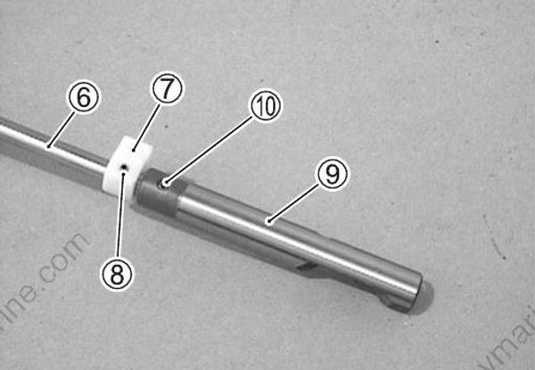
Attach lower shift rod guide (7) to shift rod (6), then secure it with the pin (8).
Attach shift cam (9) to shift rod, then insert pin (10).
Slide the shift rod through shift rod guide.
DETENT BALL
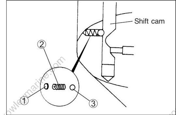
Insert the plate (1), spring (2) and detent ball (3) into gearcase.
FORWARD GEAR
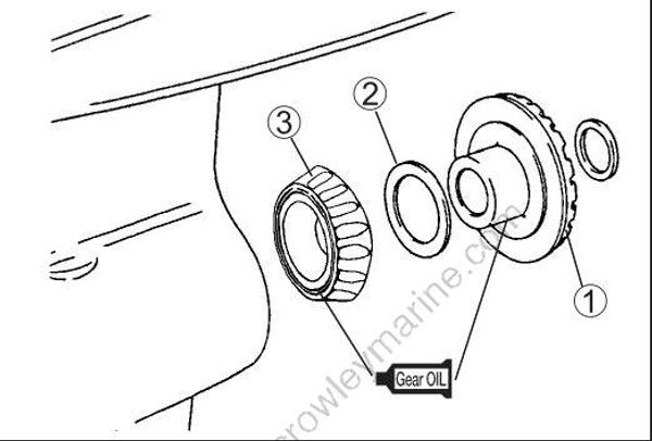
Place the forward gear bearing (3) and back-up shim (2) in position, then install forward gear (1).
99000-22540 : Suzuki Outboard Motor Gear Oil
DRIVESHAFT THRUST WASHERS
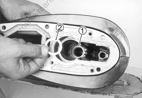
Install the two driveshaft thrust washers (1), (2).
The lower washer (with the tab) is located as shown.
DRIVESHAFT SPRING COLLAR
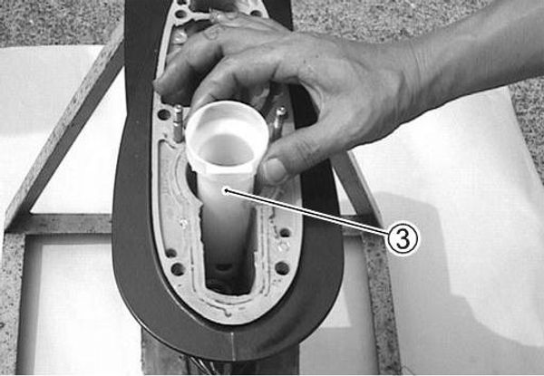
Install the collar (3) on top of the two thrust washers.
PINION GEAR
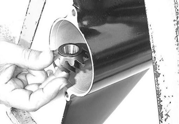
Place pinion gear in gearcase.
DRIVESHAFT
Slide on the pre-load spring (1) and secure it with the pin (2).
Assemble the thrust bearing (3), washer (4) and pinion shim (5) to the driveshaft.
Lower the driveshaft assembly down into the gearcase until the bottom of shaft protrudes through center of pinion.

DRIVESHAFT BEARING HOUSING
Apply Water Resistant Grease to the driveshaft oil seal.
99000-25161 : Water Resistant Grease
Install the gearcase seal ring (1) into the groove on the driveshaft bearing housing.
Apply Suzuki Silicone Seal to gearcase and driveshaft bearing housing surfaces.
99000-31120 : Suzuki Silicone Seal

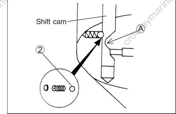
Install complete housing and shift rod assembly on gearcase.
Be sure the stepped section (A) of shift cam faces towards propeller shaft.
Also be sure the rear side of the shift cam (with detent notch) is positioned over the detent ball (2) in the gearcase.
PINION NUT
Apply Thread Lock 1342 to the threads of the pinion nut before threading it onto the driveshaft.
Tighten nut to the specified torque.
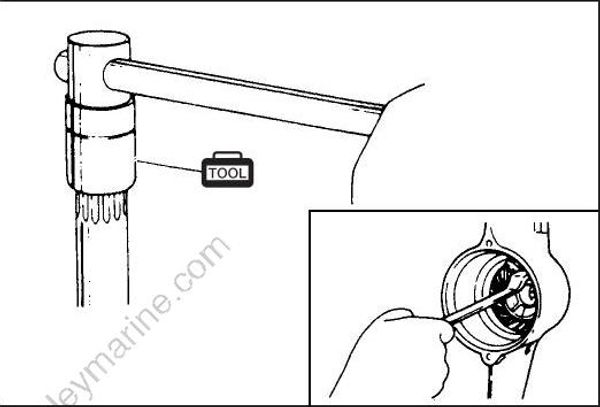
Pinion nut : 50 N . m (5.0 kg-m, 36.2 lb.-ft.)
99000-32050 : Thread Lock 1342
09921-29511 : Drive shaft holder
CHECKING DRIVESHAFT THRUST PLAY
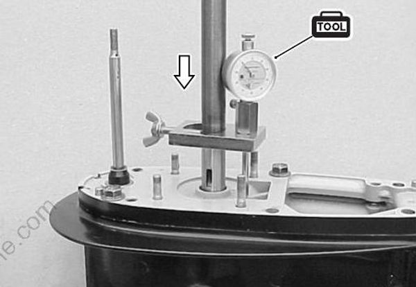
Before installing reverse gear, driveshaft thrust play should checked.
(See the “GEARS-SHIMMING AND ADJUSTMENT / CHECK ING DRIVESHAFT THRUST PLAY” section on page 9-26)
09951-09530 : Gear adjusting gauge
PROPELLER SHAFT
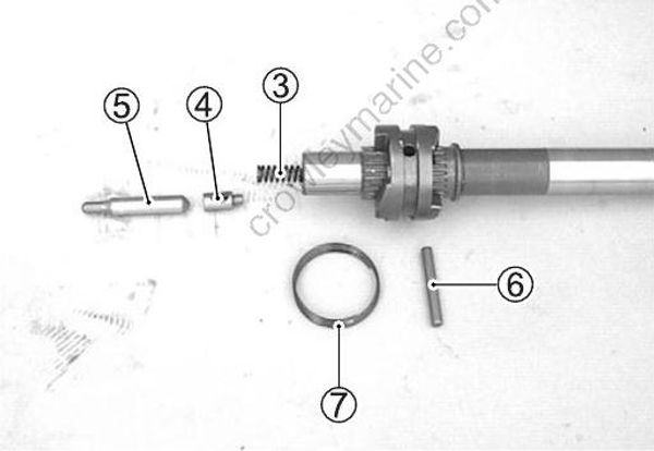
Slide the clutch dog shifter (2) onto the propeller shaft (1).
For correct installation the side of the clutch dog shifter which must face towards forward gear is marked with the letter “F”.

Insert the return spring (3), push pin (4) and push rod (5) into propeller shaft.
Align the holes in the shifter dog and push pin. Depress the push rod and slide the dog pin (6) through both dog and push pin.
Install the dog pin retaining spring (7), ensuring that it fits snuggly into the groove on the dog shifter.
PROPELLER SHAFT / BEARING HOUSING
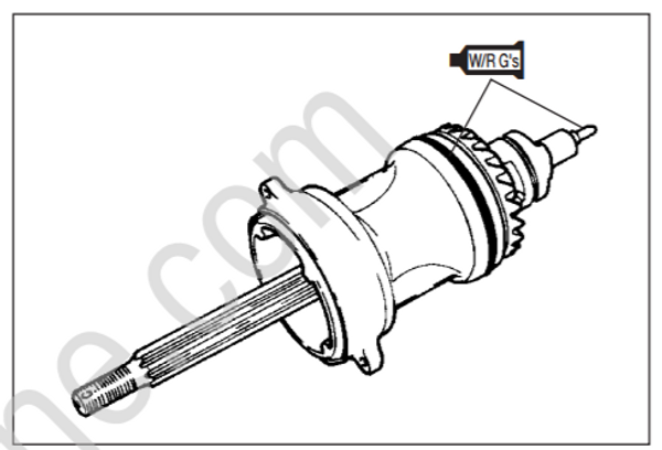
Assemble the propeller shaft in the following sequence:
forward thrust washer (5), reverse thrust washer (1), reverse gear (2), reverse gear back-up shim (3) and propeller shaft housing (4).

99000-25161 : Water Resistant Grease
99000-22540 : Suzuki Outboard Motor Gear Oil
Using special tools, install the propeller shaft and housing assembly in the gear case.
09922-59410 : Propeller shaft housing installer
09922-59420 : Housing Installer Handle
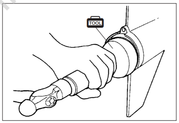
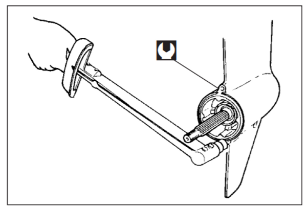
When the housing is fully seated, tighten both retaining bolts to the specified torque.
Bearing housing bolt : 17 N . m (1.7 kg-m, 12.5 lb.-ft.)
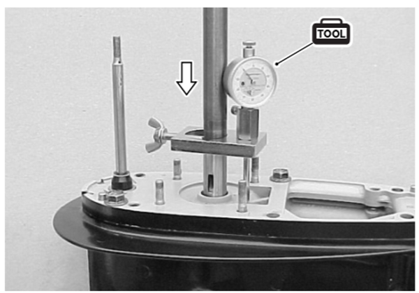
RECHECKING DRIVESHAFT THRUST PLAY
Recheck the driveshaft thrust play.
This should not be less than previously checked. If less, reduce the number / thickness of reverse gear back-up shims.
09951-09530 : Gear adjusting gauge
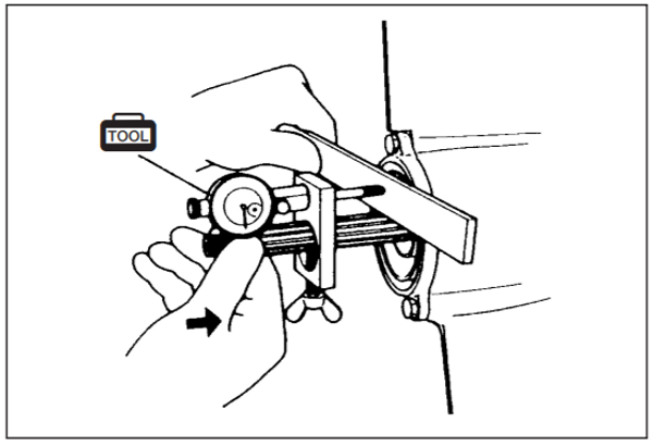
CHECKING PROPELLER SHAFT THRUST PLAY
See the “GEARS - SHIMMING AND ADJUSTMENT / CHECKING PROPELLER SHAFT THRUST PLAY” section on page 9-27.
LEAKAGE CHECK
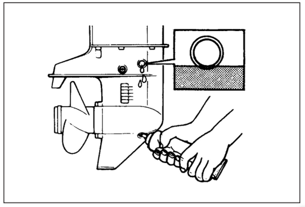
To check for oil seal or o-ring leakage, use oil leakage tester.
Before leakage check, temporarily fasten the driveshaft bearing housing to gearcase using two bolts and nuts (placed through the two diagonally opposite gearcase mounting holes).
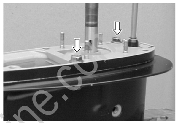
Apply the specified pressure through the oil level hole and rotate the drive and propeller shafts.
If pressure does not fall, sealing performance is correct.
09950-69512 : Oil leakage tester
09952-99310: Air pump
Leakage test pressure : 100 kPa (1.0 kg/cm², 14.2 psi)
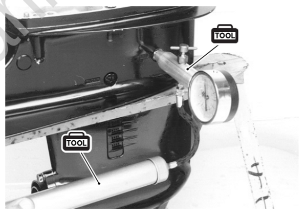
Apply low initial pressure of 0.2 – 0.4 kg / cm2, (2.8 – 5.7 psi) first, then apply specified pressure.
Do not exceed pressure of 110 kPa (1.1kg/cm², 15.6 psi) or damage to oil seals will result.
WATER PUMP ( Impeller & Case )
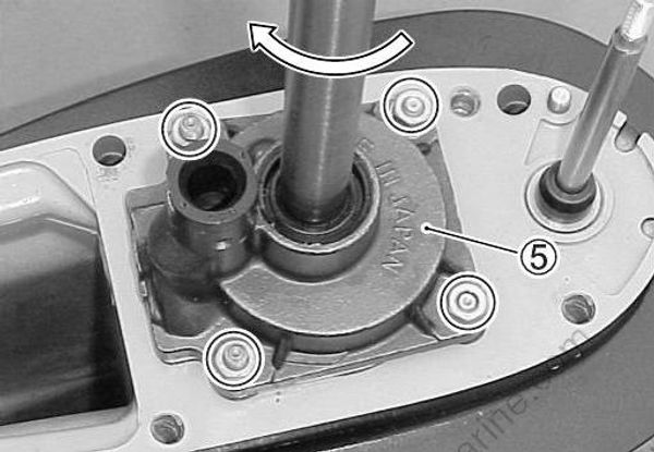
Place the under panel gasket (1) and under panel (2) into position.
Insert the key (3) in the driveshaft and slide the impeller (4) onto driveshaft, ensuring that key and keyway are aligned.

Install the pump case (5) while rotating driveshaft clockwise to flex the impeller vanes in the correct direction.
Securely tighten the four (4) pump case nuts to the specified torque.
Pump case nut : 8 N . m (0.8 kg-m, 6.0 lb.-ft.)
PROPELLER INSTALLATION
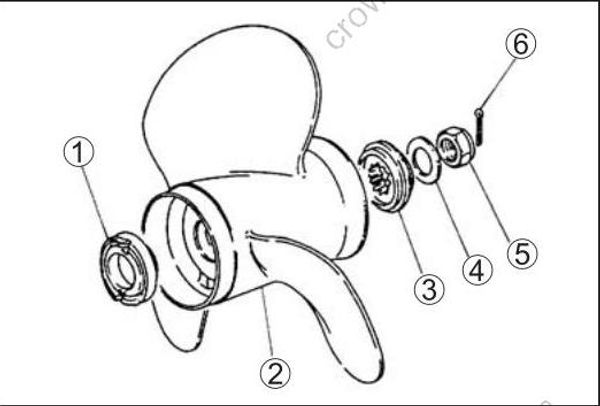
Install propeller stopper (1) onto propeller shaft, then slide on the propeller (2).
Fit spacer (3), washer (4) and nut (5), then tighten nut to specified torque.
Push cotter pin (6) through nut and shaft, then bend to secure.
99000-25161 : Water Resistant Grease
Propeller nut : 55 N . m (5.5 kg-m, 40.0 lb.-ft.)
LOWER UNIT INSTALLATION
Insert dowel pins (1).
Coat the driveshaft splines with Water Resistant Grease.
Apply a light coat of Suzuki Silicone Seal to mating surfaces of gearcase and driveshaft housing.

Slide the lower unit (2) into place, making sure that the top of the driveshaft engages properly with the crankshaft and that water tube locates in the water pump case outlet.
Apply Suzuki Silicone Seal to the retaining bolts 3 and tighten them to specified torque.
99000-25161 : Water Resistant Grease
99000-31120 : Suzuki Silicone Seal
Gearcase bolt : 23 N . m (2.3 kg-m, 16.5 lb.-ft.)
Apply Suzuki Silicone Seal to the six (6) gearcase bolts
GEAR OIL
Fill the gearcase with specified gear oil.
(See the “PERIODIC MAINTENANCE / GEAR OIL” section on page 2-5.)
99000-22540 : Suzuki Outboard Motor Gear Oil
CLUTCH ADJUSTMENT
Connect clutch rod to shift rod as shown.
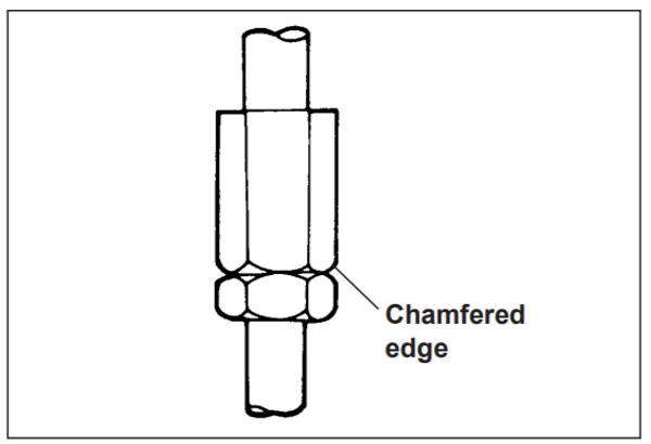
Make sure that chamfered edge of the turnbuckle faces downward to seat against the lower nut when tightened.
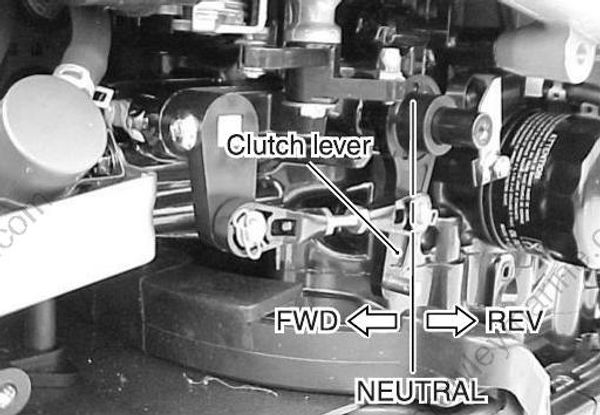
Adjustment step :
- Shift the clutch lever from Neutral through Forward and Re verse to check that proper engagement of both gears is at an equal angle from Neutral.
If Forward gear engages earlier (at a smaller angle) than Reverse, the turnbuckle should be rotated clockwise until both gears engage with the same amount of clutch lever travel.
If Reverse gear engages earlier than Forward, the turn buckle should be rotated counterclockwise.
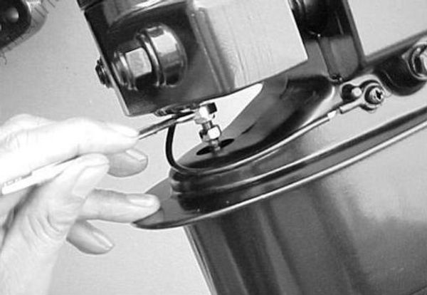
- Lock the lower nut securely against the turnbuckle when clutch lever adjustment is correct.
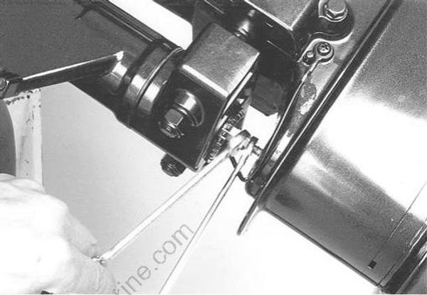
TRIM TAB
Adjusting
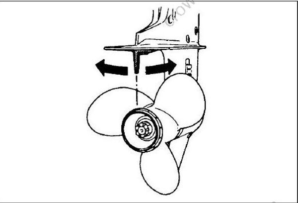
The trim tab counteracts or minimizes propeller torque “pull” felt through the steering system.
To compensate for a veer to starboard, set trailing edge of tab to the right (as viewed from behind).
To compensate for a veer to port, set trailing edge of tab to the left.
With a properly adjusted trim tab, steering will be neutral meaning there should be no tendency for the steering to “pull” to either port or starboard.