

Selective Rotation Unit
Diagnostic Information and Procedures
Diagnose Lower Unit Malfunction
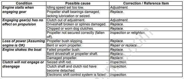
Trouble Check Chart
Service Instructions
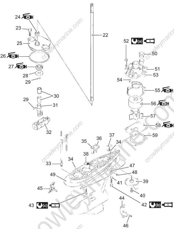
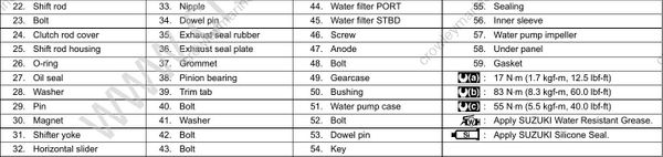
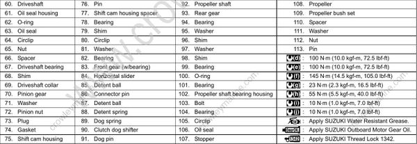
Lower Unit Components
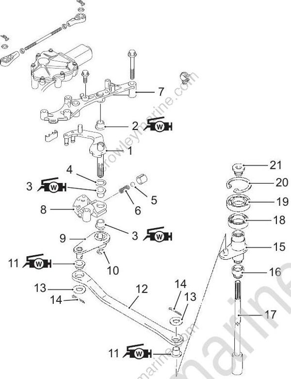
1.Clutch lever
2.Bushing
3.Bushing
4.Washer
5.Ball
6.Spring
7.Clutch holder
8.Clutch lever holder
9.Clutch shaft arm
10.E-ring
11.Bushing
12.Clutch lever link
13. Washer
14.Pin
15.Clutch shaft
16.Clutch rod cover
17.Clutch rod
18.Oil seal
19. Bearing
20.Circlip
21.Plug
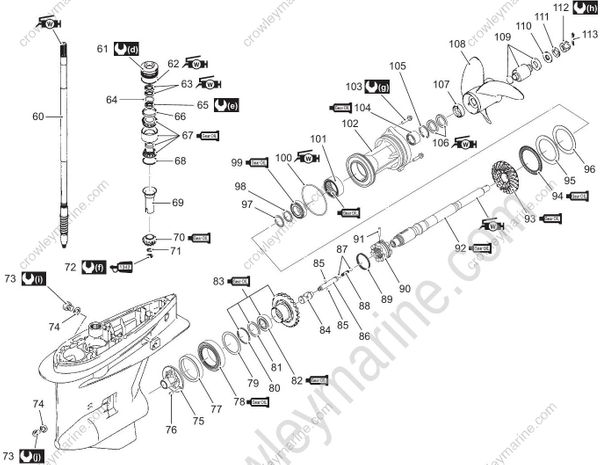
Propeller Removal and Installation
Failure to take proper precautions when installing or removing the propeller can result in severe personal injury.
When installing or removing the propeller:
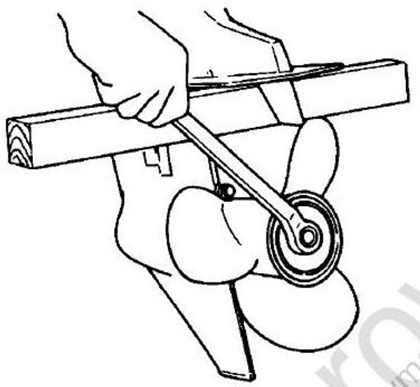
• Shift into neutral and remove the emergency stop switch lock plate so that the motor cannot be started accidentally.
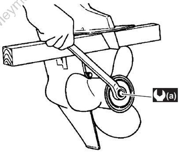
• Wear gloves to protect hands, and lock the propeller by placing a block of wood between the propeller blade tips and the anti-cavitation plate before attempting to remove or install propeller nut.
Removal
Shift to neutral position.
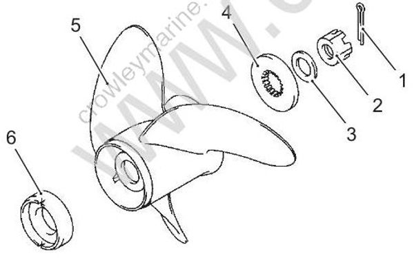
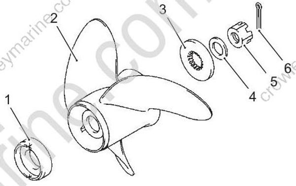
Remove cotter pin (1) from propeller nut and remove propeller nut (2).
Remove washer (3), spacer (4), propeller (5) and stopper (6) from the propeller shaft.
Installation
- Coat the propeller shaft splines liberally with Suzuki water resistant grease.
Grease 99000–25350 (SUZUKI Water Resistant Grease EP2 (250 g))
Install propeller stopper (1) onto propeller shaft, then slide on the propeller (2).
Fit spacer (3), washer (4) and nut (5), then tighten nut to specified torque.
Push cotter pin (6) through nut and shaft, then bend to secure.
Tightening torque
Propeller nut (a): 55 N•m (5.5 kgf•m, 40.0 lbf•ft)
Propeller / Propeller Nut / Cotter Pin Inspection
Refer to “Propeller / Propeller Nut and Cotter Pin Inspection” in Section 0B (Page 0B-19).
Lower Unit Removal and Installation
Removal
Failure to take proper precautions when removing or installing the lower unit can result in severe personal injury.
Always disconnect the battery cable, before removing lower unit.
Remove STBD lower side cover.
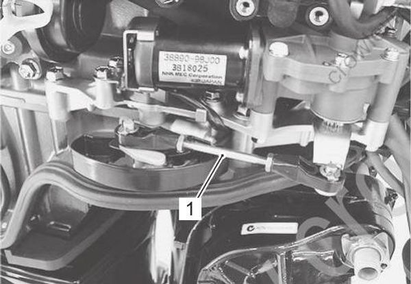
Refer to “Lower Side Cover Removal and Installation” in Section 2A (Page 2A-3).Remove the clip, washer and clutch link rod (1) from clutch control lever.
Removing the clutch link rod in an inappropriate procedure can result the electronic shift system failure. Remove the main relay or shift actuator fuse from fuse box before removing clutch link rod to avoid shift actuator damage.
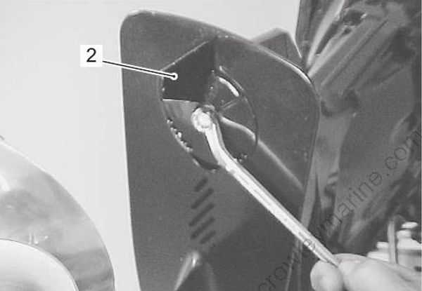
- Shift to neutral position. Remove bolt and trim tab (2).
- Remove seven bolts (3) and separate gearcase (4) from driveshaft housing.
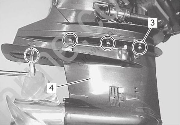
- Remove clutch rod (5) from clutch shaft (if necessary).
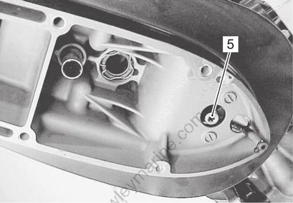
Installation
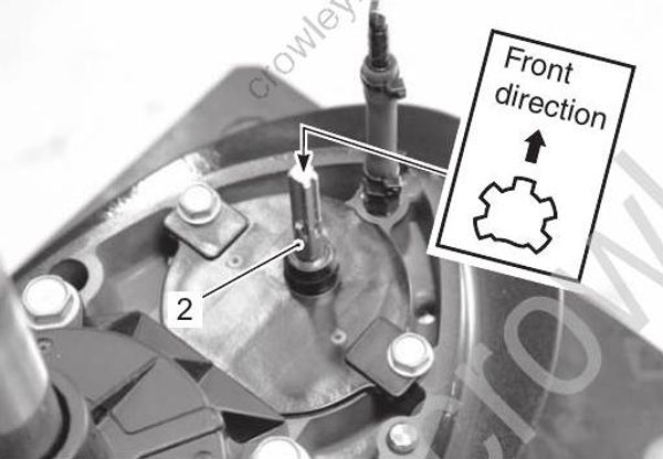
- Apply water resistant grease to clutch rod splines, then install clutch rod (1) by aligning clutch rod splines with splines in clutch shaft.
Grease 99000–25350 (SUZUKI Water Resistant Grease EP2 (250 g))
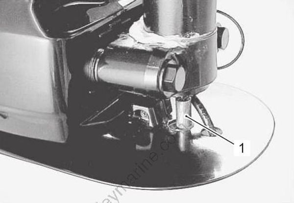
- Ensure that shift rod (2) is at neutral position.
Before installing lower unit, bring shift to Neutral position by turning shift rod right or left.
Insert two dowel pins (3).
Apply water resistant grease to driveshaft and shift rod splines.
Apply a light coating of silicone seal to mating surfaces of gearcase and driveshaft housing.
Sealant 93691–80030 (SUZUKI Silicone Seal (100 g))
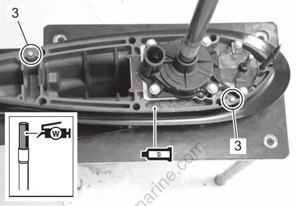
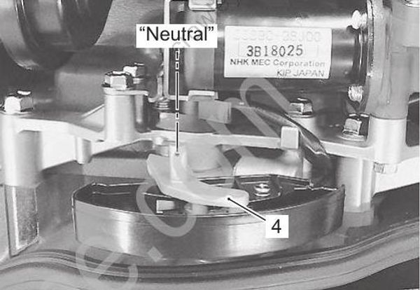
- Set the clutch control lever (4) at neutral position, then slide the lower unit (5) into place, ensuring that the top of driveshaft engages properly with driven gear shaft and that water tube locates in water pump case outlet.
In order for shift rod and clutch rod splines to be aligned correctly, clutch rod may need to be turned slightly right or left.
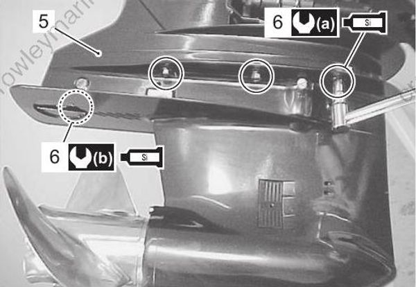
- Apply silicone seal to seven gearcase bolts (6) and tighten them to specified torque.
Sealant 93691–80030 (SUZUKI Silicone Seal (100 g))
Tightening torque
Gearcase bolt (10 mm) (a): 55 N•m (5.5 kgf•m, 40.0 lbf•ft)
Gearcase bolt (12 mm) (b): 83 N•m (8.3 kgf•m, 60.0 lbf•ft)
Shift the clutch control lever to forward and reverse position from neutral position to check proper gear engagement.
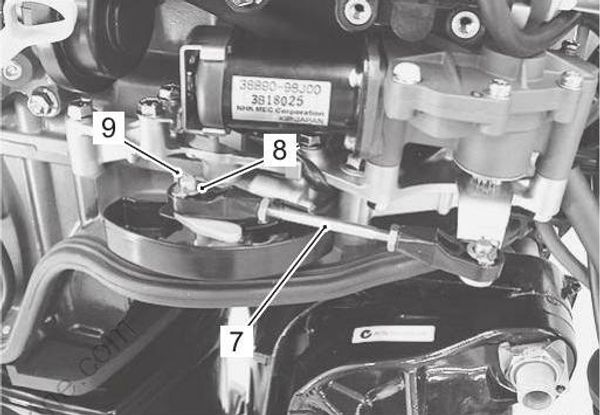
Connect the clutch link rod (7), then install washer (8) and clip (9).
Water Pump Removal and Installation
Removal
Remove the lower unit.
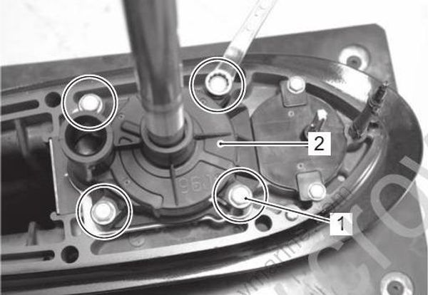
Refer to “Lower Unit Removal and Installation” (Page 3C-6).Loosen four bolts (1), then remove water pump case (2).
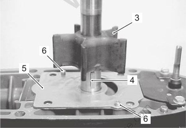
- Remove impeller (3), impeller key (4), pump under panel (5) and dowel pins (6).
Keep impeller key (4) for reuse and discard the plate gasket.
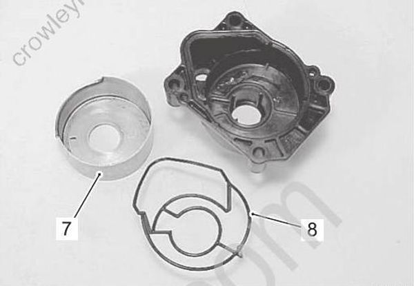
- Remove inner sleeve (7) and rubber sealing (8).
To facilitate the removal of inner sleeve from the pump case, warm up the entire case using a heater like hair dryer.
Installation
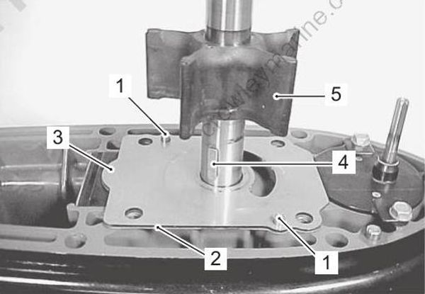
Place the dowel pins (1), under panel gasket (2) and under panel (3) into position.
Insert the key (4) in the driveshaft and slide the impeller (5) onto driveshaft, ensuring that key and keyway are aligned.
- Place the sealing (7) into groove of the pump case (6).
Do not reuse sealing once removed. Always use new sealing.
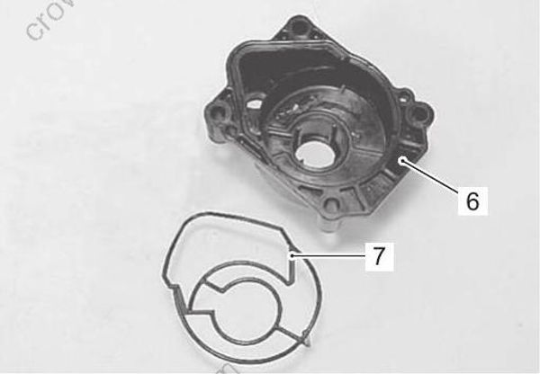
- Install inner sleeve (8) into the pump case, ensuring that projection of inner sleeve and groove of pump case are aligned.
Before installing pump inner sleeve, apply water resistant grease lightly between inner sleeve and pump case mating surfaces.
Grease 99000–25350 (SUZUKI Water Resistant Grease EP2 (250 g))
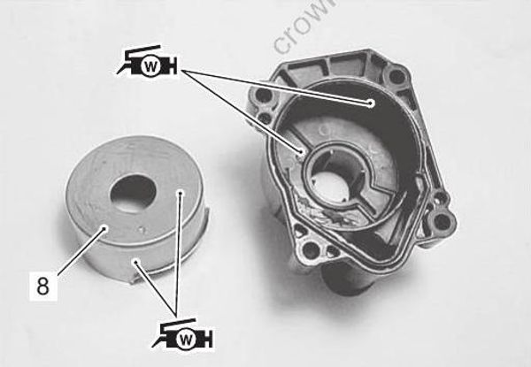
Before installing water pump case assembly, apply water resistant grease lightly on pump case inner sleeve and under panel for initial lubrication.
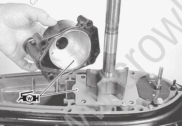
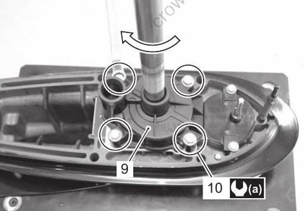
- Install the pump case assembly (9) while rotating driveshaft clockwise to flex the impeller vanes in the correct direction.
Securely tighten the four pump case bolts (10) to the specified torque.
Tightening torque
Water pump case bolt (a): 17 N•m (1.7 kgf•m, 12.5 lbf•ft)
- Install the Lower Unit.
Refer to “Lower Unit Removal and Installation” (Page 3C-6).
Water Pump and Related Item Inspection
Inspect the following parts.
- Inspect impeller. Replace if vanes are cut, torn, worn or other abnormal conditions.
- Inspect pump case. Replace if cracked, distorted or other abnormal conditions are noted.
- Inspect pump inner sleeve. Replace if worn, cracked, distorted, corroded or other abnormal conditions are noted.
- Inspect under panel. Replace if cracked, distorted, corroded or other abnormal conditions are noted.
Do not reuse sealing once removed. Always use new sealing.
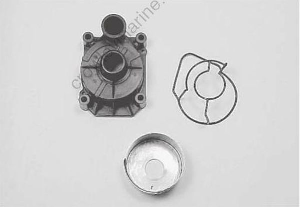
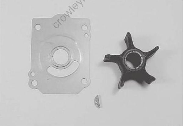
Lower Unit Disassembly
Remove the lower unit.
Refer to “Lower Unit Removal and Installation” (Page 3C-6).Remove the propeller.
Refer to “Propeller Removal and Installation” (Page 3C-5).Remove the water pump and related parts.
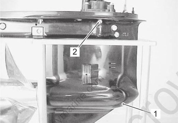
Refer to “Water Pump Removal and Installation” (Page 3C-8).Place a drain pan under oil drain plug. Remove oil drain plug (1) first then air vent plug (2) and allow gear oil to drain.
Inspect oil for water, contaminates or metal.The air vent plug, oil level plug and the oil drain plug are now different. The magnet is installed in the drain plug. Clean the magnet if there is a metal powder on it. Do not make a mistake in their positions when install them.
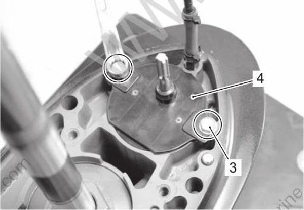
- Remove two bolts (3) and shift rod guide housing assembly (4).
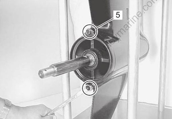
- Remove two bolts (5) securing the propeller shaft bearing housing to the gearcase.
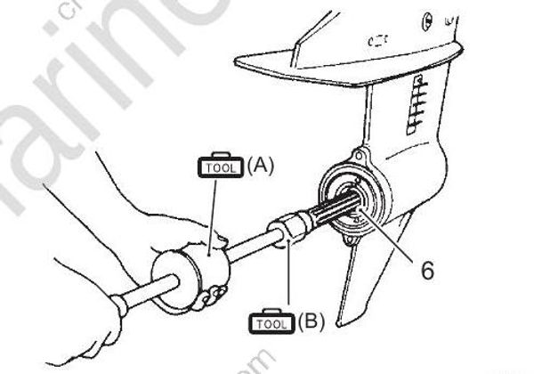
- Using special tools, pull out the propeller shaft bearing housing. Remove the propeller shaft and bearing housing assembly (6).
Special tool
(A): 09930–30104 (Sliding hammer)
(B): 09930–30161 (Propeller shaft remover)
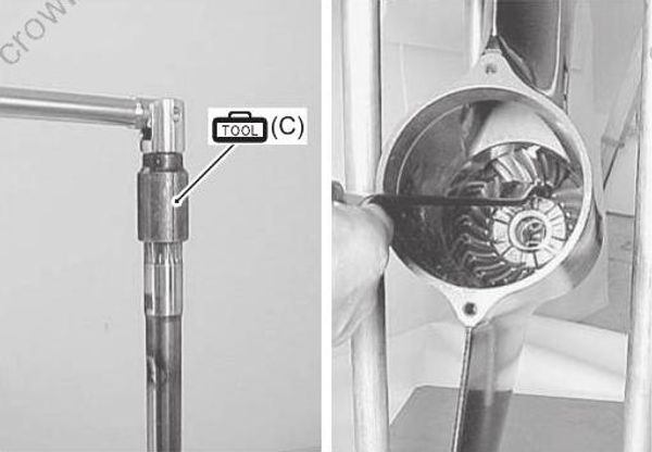
- Hold the pinion nut securely, then fit special tool to the driveshaft and loosen the pinion nut (7). Remove pinion nut (7) and washer (8).
Special tool
(C): 09921–29410 (Driveshaft holder)
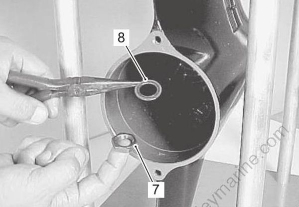
- Use special tool to unscrew driveshaft oil seal housing (9), then remove oil seal housing from driveshaft.
Special tool
(D): 09926–29310 (Driveshaft housing remover)
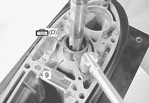
- Remove driveshaft bearing spacer (10).
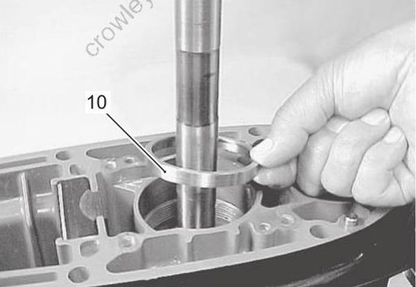
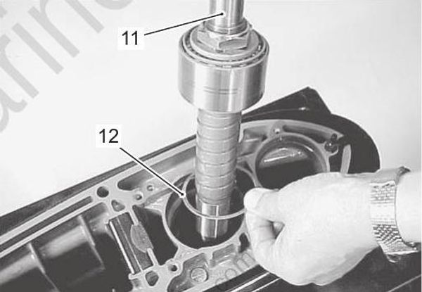
Slowly lift out driveshaft assembly (11).
Remove the pinion shim (12).The driveshaft pinion gear bearing contains 22 loose roller bearings. Account for all roller bearings on disassembly.
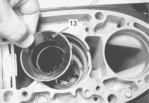
- Remove the driveshaft collar (13).
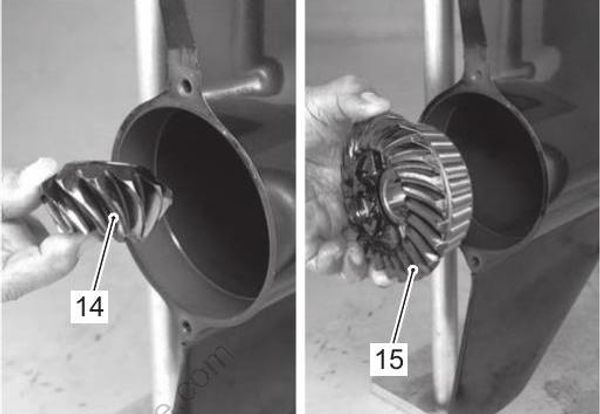
- Remove the pinion gear (14).
Remove the front gear (15) (with thrust bearing).
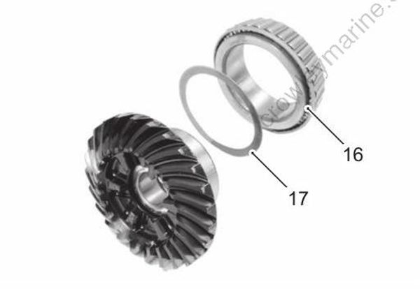
- Remove the thrust bearing (16) and back-up shim (17) from front gear.
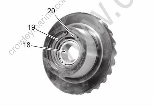
Front gear, propeller shaft bearing (18), circlip (19) and washer (20) are a set. If any repair is required on the propeller shaft bearing or front gear, replace them as a pinion/gear set.
- To disassemble propeller shaft components, refer to following.
a) Slide propeller shaft (21) away from rear gear (22) and bearing housing assembly (23).
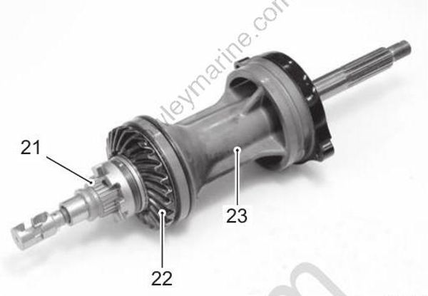
b) Remove the rear gear (22), rear gear thrust bearing (24), rear gear thrust washer (25) and rear gear back-up shim (26).
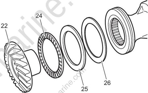
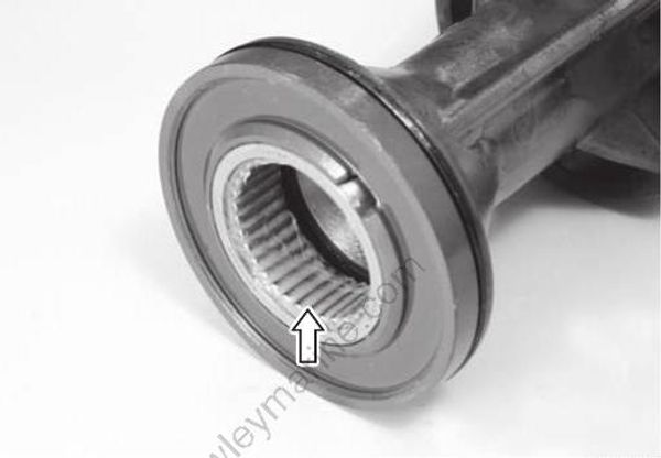
c) Before removing the thrust bearing, take out the loose roller bearings from bearing housing.
The rear gear radial bearing contains 35 loose roller bearings. Account for all roller bearings on disassembly.
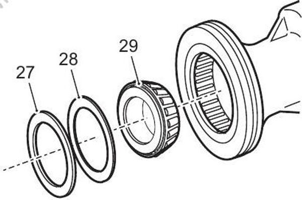
d) Remove the propeller shaft thrust washer (27), propeller shaft thrust shim (28) and bearing (29) from propeller shaft bearing housing.
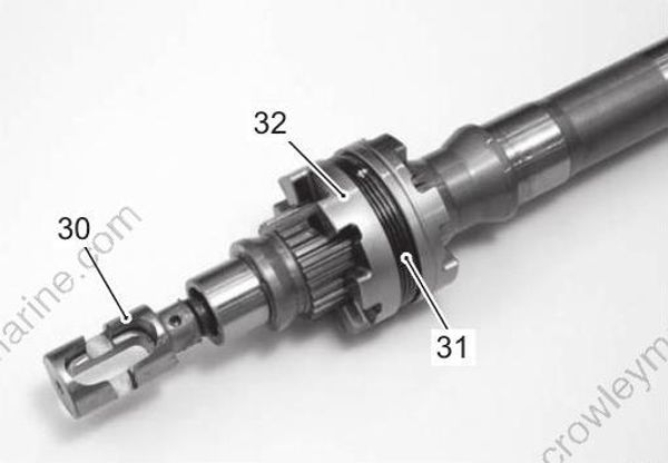
e) Remove horizontal slider (30).
Remove the spring (31) from the clutch dog shifter (32).
f) Use special tool to push the dog pin (33) out of the clutch dog shifter (32).
Special tool
(E): 09922–89810 (Shift lock pin remover)
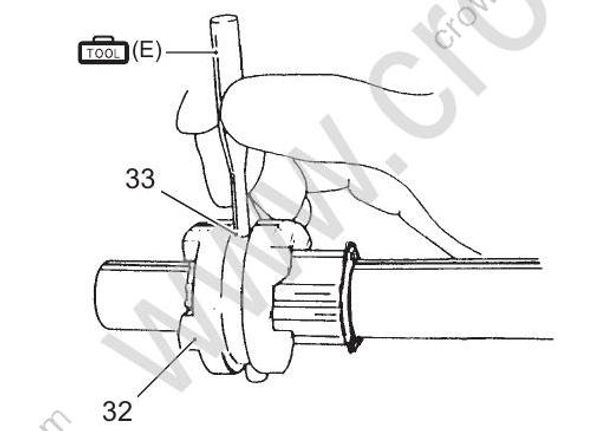
g) Remove the clutch dog shifter (32) and connector pin (34) from propeller shaft.
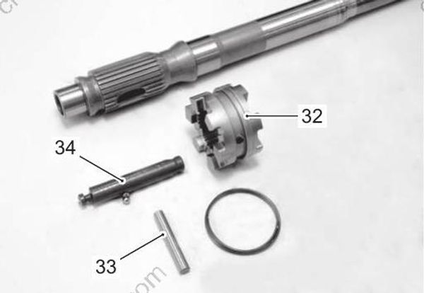
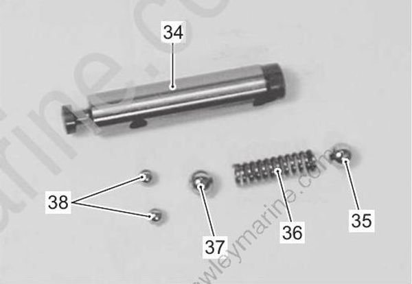
h) Remove large detent ball (35), detent spring (36), large detent ball (37) and two small detent balls (38) from connector pin (34).
- To disassemble shift rod components, refer to following.
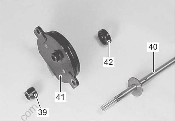
a) Remove dust seal (39).
b) Slide shift rod (40) out of shift rod guide housing (41).
c) Draw the oil seal (42) out of shift rod guide housing (41).
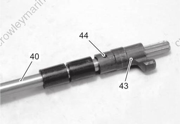
d) Separate the shifter yoke (43) from shift rod (40) by driving out the pin (44).
Lower Unit Related Item Inspection
Failure to following proper precautions during use of the compressed air may cause severe personal injury. Wear safety glasses when using compressed air.
• If any component is worn excessively, cracked, defective or damaged in any way, it must be replaced.
• Thoroughly wash all metal components with cleaning solvent and dry with compressed air.
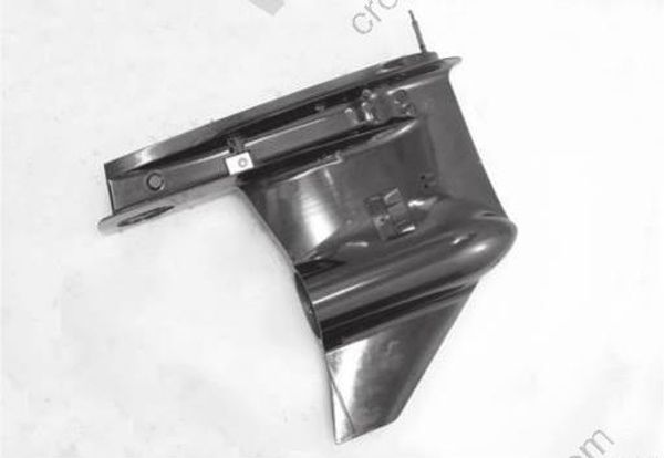
Gearcase
Inspect the gearcase. Replace if cracked, damaged or other abnormal conditions are noted.
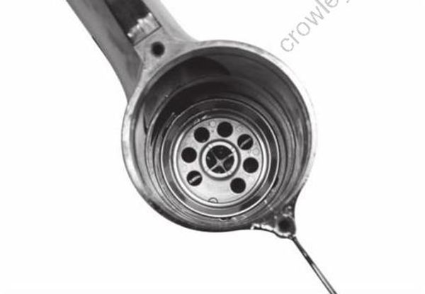
Visually check the pinion bearing. Replace gearcase if pitted, rough or other abnormal conditions are noted.
Visually check shift cam housing.
Replace gearcase if cracked, damaged or other abnormal conditions are noted.
Gears / Bearing
- Inspect front, rear and pinion gear teeth and engaging dogs.
- Replace gears if damaged, worn or other abnormal conditions are noted.
- Inspect front gear bearing and propeller shaft front bearing.
Replace bearing if pitted, noisy, rough or other abnormal conditions are noted.
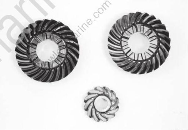
Front gear, propeller shaft front bearing, circlip and washer are a set. If any repair is required on the propeller shaft bearing or front gear, replace them as a pinion/gear set.
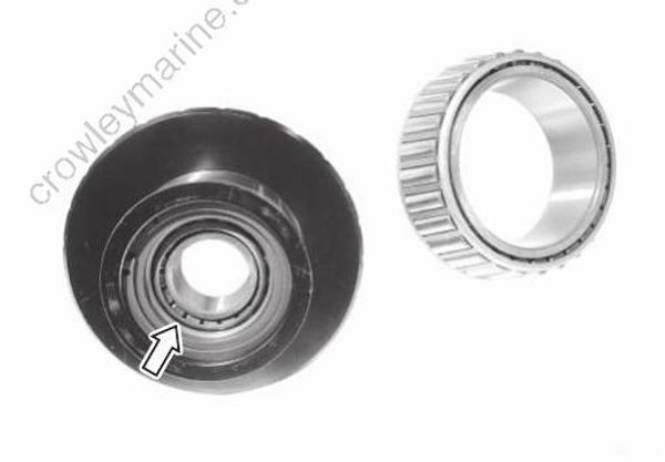
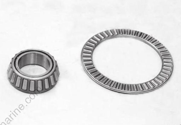
Rear gear Bearing / Propeller Shaft Bearing
- Visually check bearing. Replace if pitted, noisy, rough or other abnormal condition are noted.
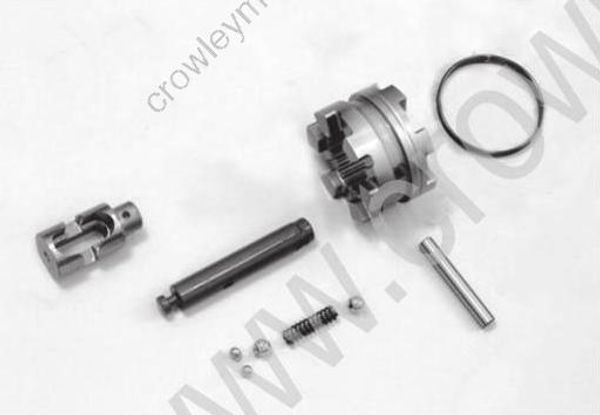
Propeller Shaft Components
- Inspect horizontal slider and connector pin.
Replace if worn, damaged or other abnormal conditions are noted. - Inspect detent balls. Replace if wear, damage or other abnormal conditions are noted.
- Inspect clutch dog shifter. Replace if chipped, worn, damaged or other abnormal conditions are noted.
- Inspect dog pin. Replace if bent, worn or other abnormal conditions are noted.
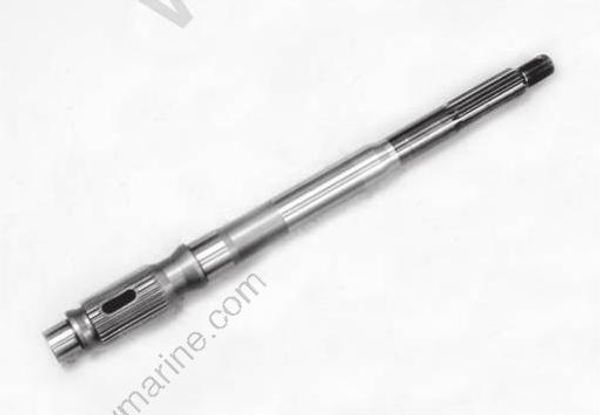
- Inspect propeller shaft/splines. Replace if worn, twisted, damaged or other abnormal conditions are noted.
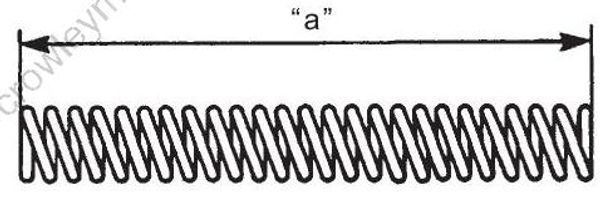
- Check detent spring by measuring its free length. If free length is not within specifications, replace detent spring.
Detent spring free length “a”
Standard: 27.8 mm (1.09 in.)
Service limit: 25.0 mm (0.98 in.)
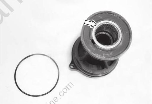
Propeller Shaft Bearing Housing
- Inspect housing. Replace if cracked, damaged or other abnormal conditions are noted.
- Inspect rear gear bearing and propeller shaft bearing. Replace bearing if pitted, noisy, rough or other abnormal conditions are noted.
- Check condition of oil seal and O-ring. Replace oil seal and O-ring if nicked, cut, worn or other abnormal conditions are noted.
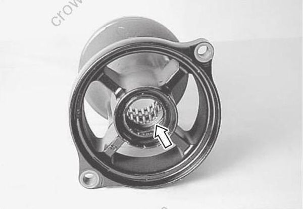
Shift Rod Guide Housing Components
- Inspect shift rod guide housing.
Replace if cracked, damaged or other abnormal conditions are noted. - Inspect shifter yoke. Replace if worn, damaged or other abnormal conditions are noted.
- Inspect shift rod/splines. Replace if worn, twisted, damaged or other abnormal conditions are noted.
- Inspect O-ring. Replace if nicked, cut, torn, swollen or other abnormal conditions are noted.
- Inspect oil seal and dust seal. Replace if nicked, cut, worn or other abnormal conditions are noted.
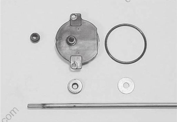
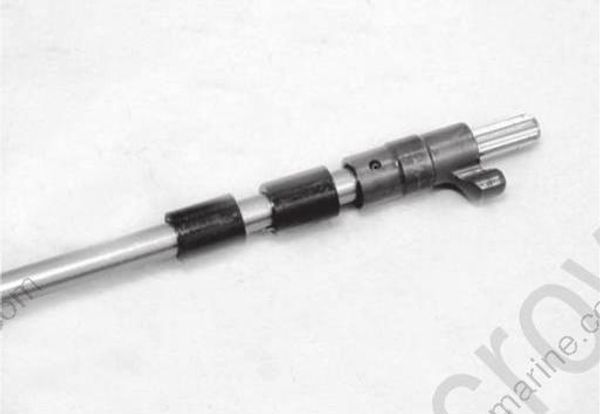
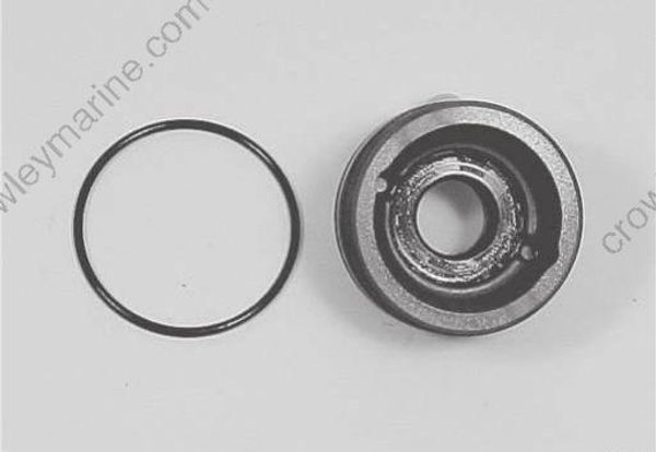
Driveshaft Oil Seal Housing
- Inspect housing. Replace if cracked, damaged or other abnormal conditions are noted.
- Check condition of oil seals. Replace if nicked, cut, worn or other abnormal conditions are noted.
- Inspect O-ring. Replace if worn, nicked, cut or other abnormal conditions are noted.
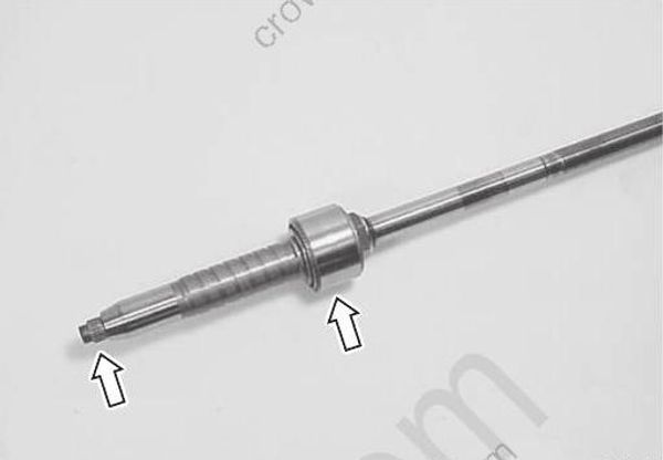
Driveshaft
- Inspect driveshaft/splines. Replace if worn, twisted, damaged or other abnormal conditions are noted.
- Inspect driveshaft bearing, replace if pitted, noisy, rough or other abnormal conditions are noted.
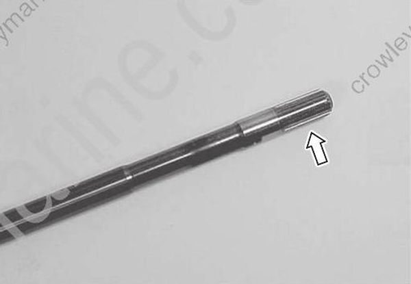
Propeller Shaft Oil Seal Replacement
Remove the propeller shaft bearing housing.
Refer to “Lower Unit Disassembly” (Page 3C-10).Extract the seals (1) with oil seal remover.
Removing the oil seal can cause damage to the seal lips, causing oil to leak. Do not reuse the oil seal once removed. Always use new one.
Special tool
(A): 09913–50121 (Oil seal remover)
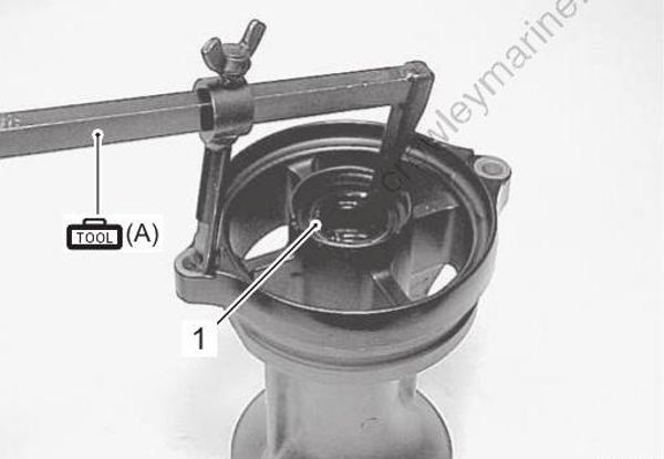
- Apply water resistant grease to the inner circumference of the housing.
Grease 99000–25350 (SUZUKI Water Resistant Grease EP2 (250 g))
- Using an oil seal installer, drive the two oil seals (one at a time) into the propeller shaft bearing housing.
The lipped portion of the seal must face towards the propeller. Apply water resistant grease to the seal lips.
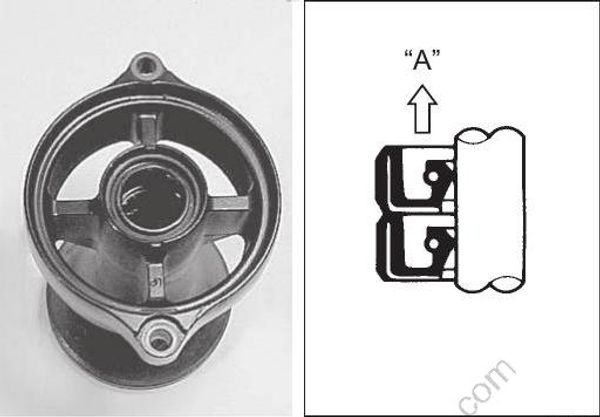
“A”: Direction of propeller
- Assemble the propeller shaft bearing housing. Refer to “Lower Unit Assembly” (Page 3C-18).
Driveshaft Oil Seal Replacement
Remove the driveshaft oil seal housing.
Refer to “Lower Unit Disassembly” (Page 3C-10).Remove the circlip (1).
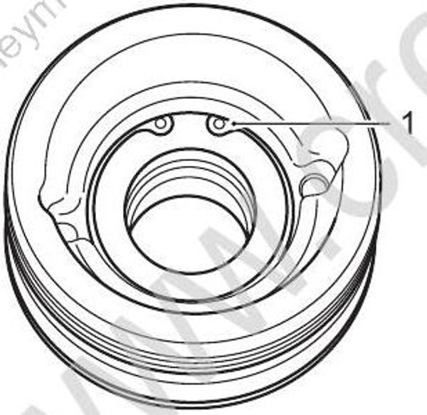
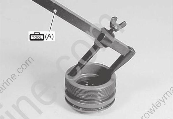
- Using special tool, remove two oil seals out of the driveshaft oil seal housing.
Special tool
(A): 09913–50121 (Oil seal remover)
Removing the oil seal can cause damage to the seal lips, causing oil to leak. Do not reuse the oil seal once removed. Always use new one.
- Apply water resistant grease to inner circumference of driveshaft oil seal housing.
Grease 99000–25350 (SUZUKI Water Resistant Grease EP2 (250 g))
Grease the inner lips of oil seal.
With the lips facing away from driveshaft bearing, place seal in position and drive it into the oil seal housing.Install the circlip (1).
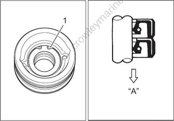
“A”: Direction of water pump case
- Assemble the driveshaft oil seal housing.
Refer to “Lower Unit Assembly” (Page 3C-18).
Lower Unit Assembly
Assembly is in reverse order of disassembly with special attention to the following steps.
Failure to correctly adjust the gear position will result in lower unit damage. Before final assembly of lower unit, be absolutely certain that all gear contact, shim adjustments and tolerances are correct. (Refer to “Lower Unit Gears - Shimming and Adjustment” (Page 3C-25).)
• Make sure that all parts used in assembly are clean and lubricated.
• It is recommended that all seals, gaskets and O-rings be replaced with new on assembly.
• After assembly, check parts for tightness and smoothness of operation.
Front Gear
- Place the back-up shim (1) and thrust bearing (2) in position, then install the front gear/bearing assembly into position.
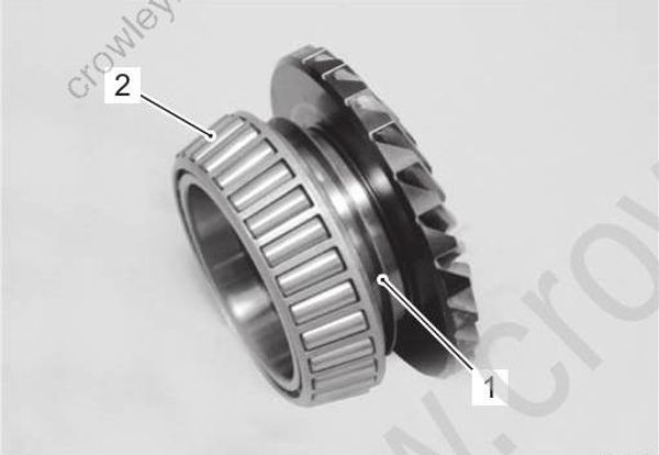
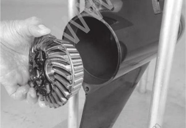
Driveshaft Collar
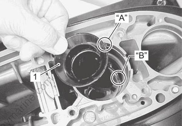
- Install driveshaft collar (1).
The tongue “A” of collar must be located into groove “B” on the gearcase.
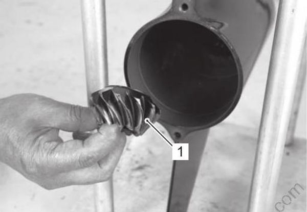
Pinion Gear
- Place pinion gear (1) in gearcase.
Before installing pinion gear, check for correct amount and position of pinion bearing rollers. Use oil soluble grease to retain bearing rollers.
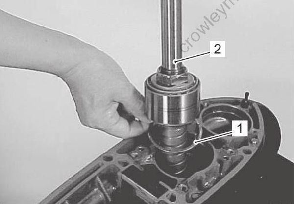
Driveshaft
- Install pinion shim (1), then lower the driveshaft assembly (2) down into the gearcase until the bottom of shaft protrudes through center of pinion.
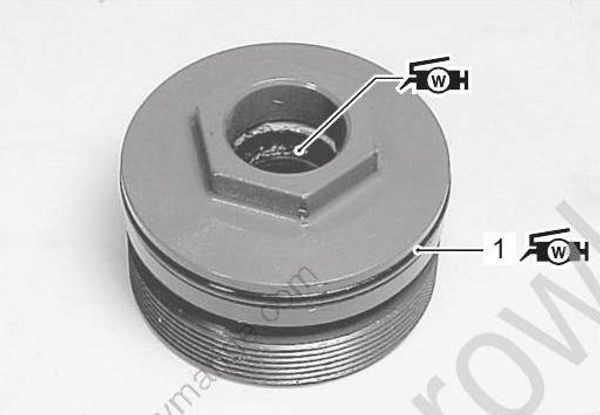
Driveshaft Oil Seal Housing
- Apply water resistant grease to the driveshaft oil seal.
- Apply water resistant grease to O-ring (1), then install O-ring into groove on the driveshaft oil seal housing.
Grease 99000–25350 (SUZUKI Water Resistant Grease EP2 (250 g))
- Install driveshaft bearing spacer (2).
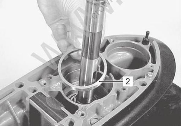
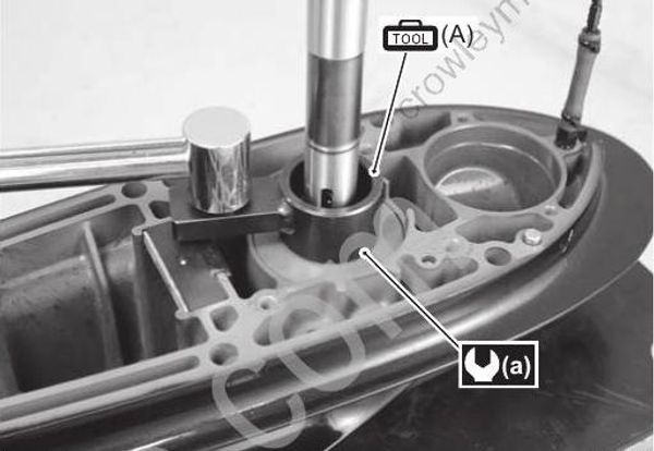
Install driveshaft oil seal housing on gearcase, then tighten oil seal housing to specified torque.
*Special tool**
*(A): 09926–29310 (Driveshaft housing remover)**
Tightening torque
Driveshaft oil seal housing (a): 100 N•m (10.0 kgf•m, 72.5 lbf•ft)
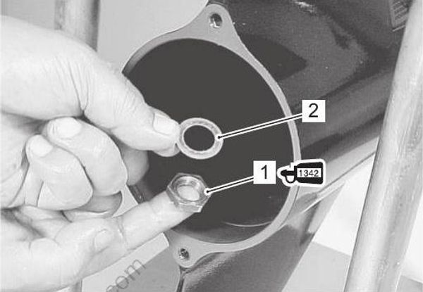
Pinion Nut
- Apply thread lock 1342 to the threads of pinion nut (1) before threading it onto driveshaft.
Thread lock cement 99000–32050 (SUZUKI Thread Lock 1342 (50 g))
It is recommended the original pinion nut be used for the purposes of shimming during repair. A new pinion nut should be used on final assembly.
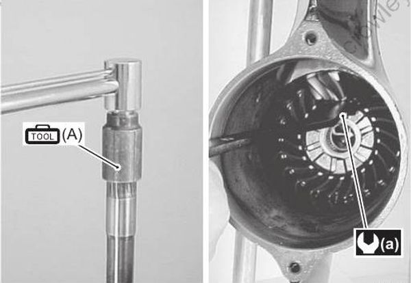
- Install the washer (2) and tighten pinion nut (1) to specified torque.
Special tool
(A): 09921–29410 (Driveshaft holder)
Tightening torque
Pinion nut (a): 145 N•m (14.5 kgf•m, 105.0 lbf•ft)
Propeller Shaft
- Slide the clutch dog shifter (1) onto the propeller shaft (2).
The marked side with identification groove “A” of the clutch dog shifter must face towards rear gear.
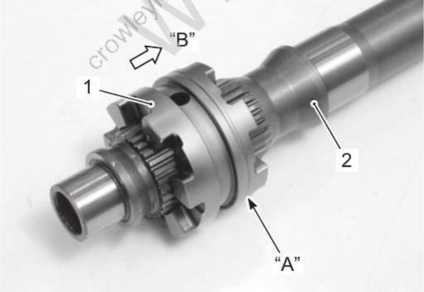
“A”: I.D. groove
“B”: Rear gear side
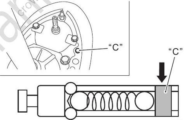
- Insert two small detent balls (3), large detent ball (4), detent spring (5) and large detent ball (6) into connector pin (7). Then depress detent ball (6) and temporarily insert stopper pin “C” into dog pin hole of connector pin, as shown in figure.
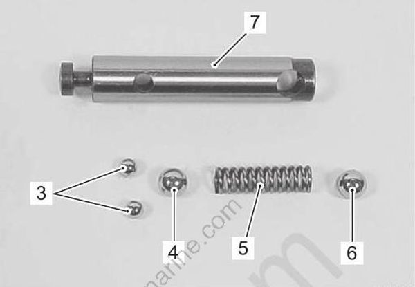
Temporarily insert a gearcase dowel pin “C” into the connector pin to prevent the detent ball from falling out.
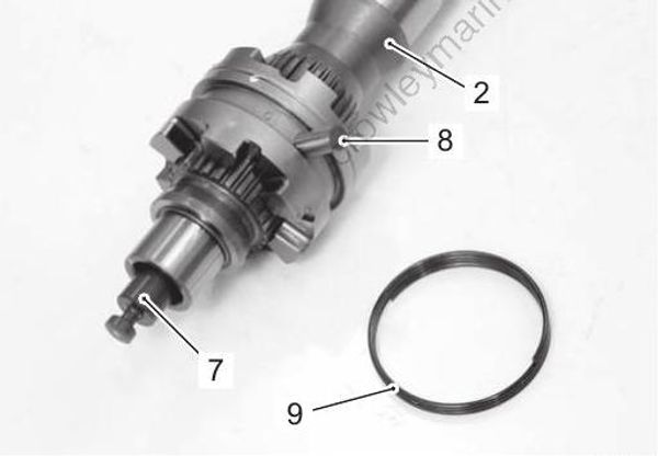
- Insert the connector pin (7) (with detent balls) into propeller shaft (2).
- Align the holes in the clutch dog shifter and connector pin and then slide the dog pin (8) through both clutch dog shifter and connector pin. (save the temporarily installed dowel pin “C” pushed out as the dog pin is inserted.)
- Install the dog pin retaining spring (9), ensuring that it fits snugly into the groove on the dog shifter.
Rear Gear / Propeller Shaft / Bearing Housing
Assemble the propeller shaft in the following sequence.
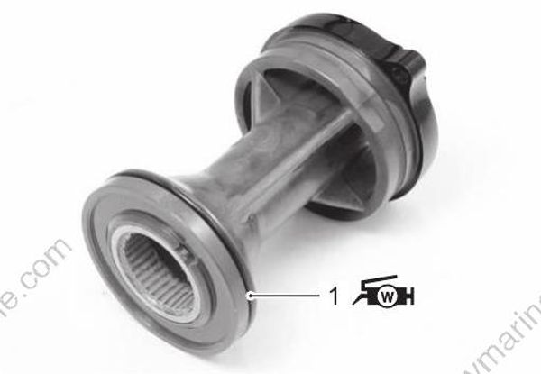
- Apply water resistant grease to O-ring (1), then install the O-ring into the groove on the propeller shaft bearing housing.
Grease 99000–25350 (SUZUKI Water Resistant Grease EP2 (250 g))
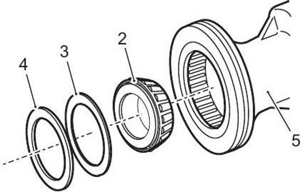
- Install the propeller shaft thrust bearing (2), shim (3) and thrust washer (4) into propeller shaft bearing housing (5).
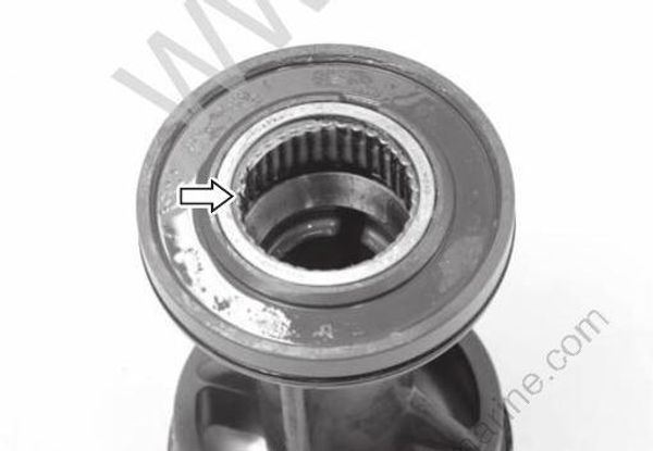
Before installing rear gear, check for correct amount and position of rear gear radial bearing rollers. Use oil soluble grease to retain bearing rollers.
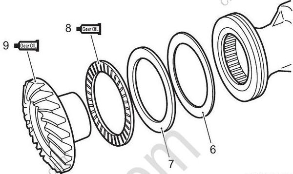
- Install rear gear back-up shim (6), rear gear thrust washer (7), rear gear thrust bearing (8) and rear gear (9) to propeller shaft bearing housing.
Gear Oil 99000–22B22 (SUZUKI Outboard Motor Gear Oil)
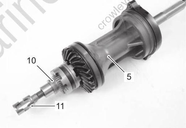
Slide propeller shaft (10) into rear gear and propeller shaft bearing housing (5).
Assemble horizontal slider (11) to connector pin.
Before installing propeller shaft/bearing housing assembly, move shifter dog to bring horizontal slider to the neutral position.
- To hold the correct bearing position, pull propeller shaft backward and then install propeller shaft and housing assembly in the gearcase with the mark “UP” of housing toward upside.
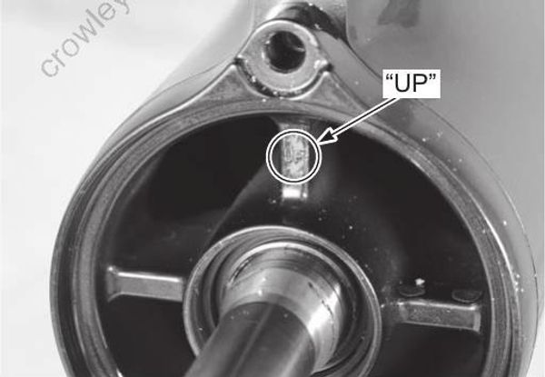
To make the bearing housing fully seated in the gearcase, tap the housing gently with plastic mallet.
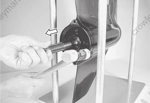
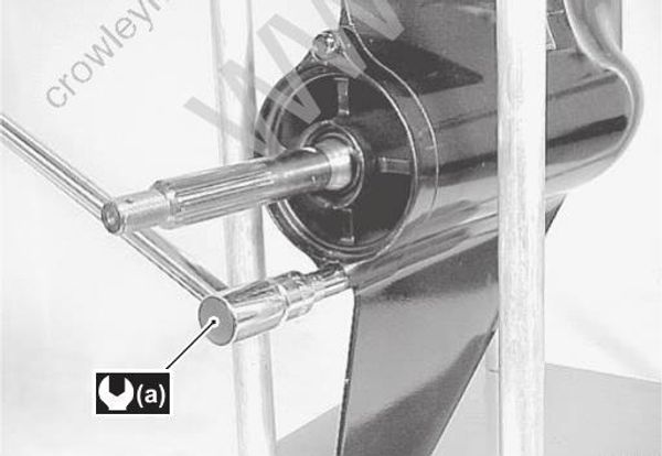
- When the housing is fully seated, tighten both retaining bolts to the specified torque.
Tightening torque
Bearing housing bolt (a): 23 N•m (2.3 kgf•m, 16.5 lbf•ft)
Checking Propeller Shaft Thrust Play
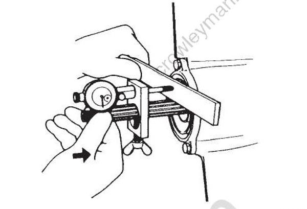
Check propeller shaft thrust play.
Refer to “Lower Unit Gears Shimming and Adjustment” (Page 3C-25).
Shift Rod Guide Housing
Apply water resistant grease to oil seal (1).
Using an oil seal installer, drive the oil seal (1) into the shift rod guide housing (2). The lipped portion of oil seal must face towards the driveshaft housing.*Grease 99000–25350 (SUZUKI Water Resistant Grease EP2 (250 g))**
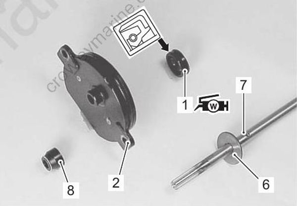
- Attach shifter yoke (3) to shift rod (4), then insert pin (5).
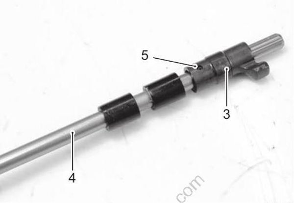
Install pin (7) and washer (6) to shift rod, then slide shift rod guide housing onto shift rod.
Install dust seal (8) to shift rod guide housing.
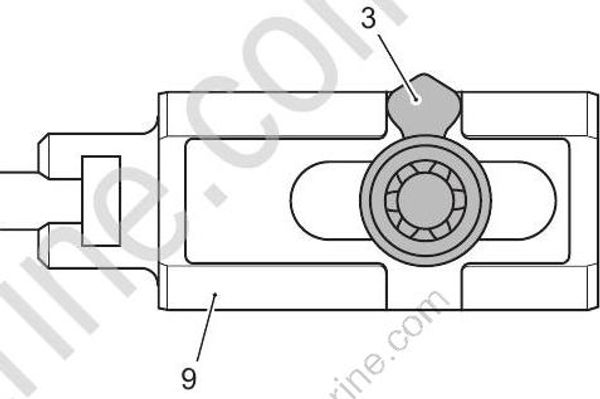
Be sure the horizontal slider (9) is in the neutral position before installing the shift unit (shift rod guide housing assembly).
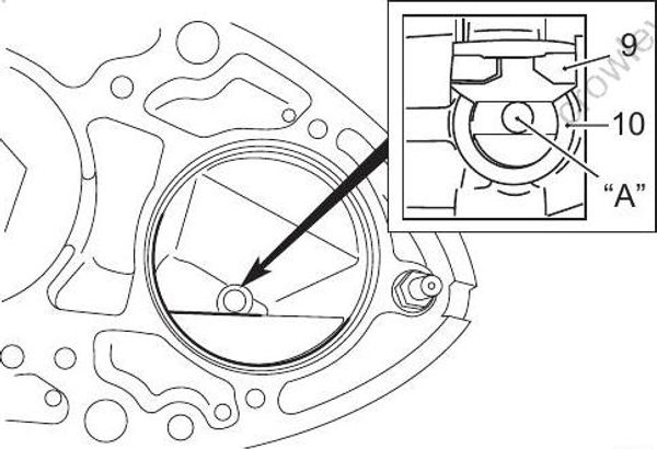
9.Horizontal slider
10.Shift cam housing
“A”: Shift rod center
- Apply water resistant grease to the shift rod guide housing O-ring.
Grease 99000–25350 (SUZUKI Water Resistant Grease EP2 (250 g))
Before installing shift rod guide housing assembly, bring shifter yoke to Neutral position by turning shift rod right or left.
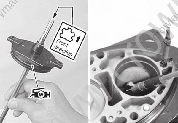
- Install shift rod guide housing assembly by aligning shifter yoke (3) with groove in horizontal slider (9), then tighten two housing bolts (11) securely.
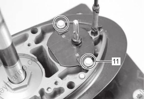
- Turn shift rod from Neutral position to Forward and Reverse position to check proper gear engagement.
Leakage Check
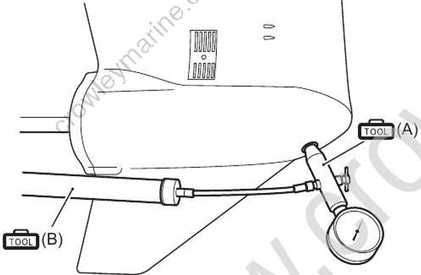
Check for leakage of oil seal and O-ring when applying specified pressure inside of the gearcase.
Install the test tool into the oil drain hole.
Connect the air pump to the tester.
Rotate driveshaft and propeller shaft clockwise several times and then apply specified pressure for the test.
Failure to correctly apply the test pressure will result in oil seal damage. Do not exceed pressure of 110 kPa (1.1 kg/cm², 15.6 psi.).
Apply low initial pressure of 20 – 40 kPa (0.2 – 0.4 kg/cm², 2.8 – 5.7 psi.) first, then apply specified pressure.
Special tool
(A): 09950–69512 (Gearcase oil leakage tester)
(B): 09952–99320 (Hand air pump)
Leakage pressure test
100 kPa (1.0 kg/cm², 14.2 psi.)
- Once stabilized, pressure should remain steady for at least 5 min.
If pressure does not fall, sealing performance is correct.
Water Pump
Install the water pump and related parts.
Refer to “Water Pump Removal and Installation” (Page 3C-8).
Propeller
Install the propeller.
Refer to “Propeller Removal and Installation” (Page 3C 5).
Lower Unit
Install the Lower Unit.
Refer to “Lower Unit Removal and Installation” (Page 3C-6).
Trim Tab Adjustment
The trim tab counteracts or minimizes propeller torque pull felt through the steering system.
If the steering is pulls to the starboard or port side, adjust the trim tab with the following procedure. 1) Loosen the trim tab bolt (1).
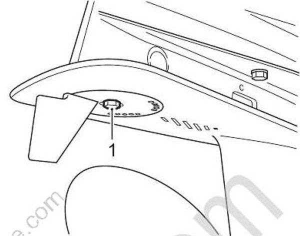
- Changing the trim tab setting.
- To compensate for a veer to starboard, set the trailing edge of tab (2) to the right (as viewed from behind).
- To compensate for a veer to port, set the trailing edge of tab (2) to the left.
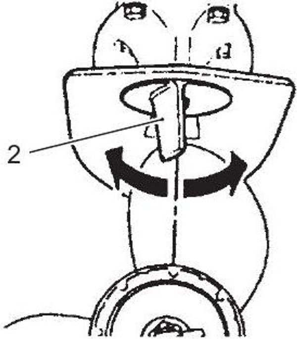
Tighten the bolt of trim tab.
Test drive the boat and repeat the procedure 1) – 3) to set the trim tab in the best position.
With a properly adjusted trim tab, steering should be neutral and there should be no tendency for the steering to be pulled to either port or starboard.
Lower Unit Gears - Shimming and Adjustment
If the lower unit has been rebuilt or has had components replaced, shimming for the correct gear contact and backlash will have to be checked and/or adjusted to ensure smooth, reliable operation.
Shim/Washer and mounting position
| Item | Available thickness (mm) | Design specification thickness (mm) |
|---|---|---|
| Pinion gear back up shim | 0.85, 0.900.45, 0.50, 0.55, 0.60, 0.65, 0.70, 0.75, 0.80, | 1.0 |
| Front gear back up shim | 0.50, 0.55, 0.60, 0.65, 0.70, 0.75, 0.80, 0.85, 0.90, 0.95 | 1.25 |
| Propeller shaft thrust shim | 0.60, 0.65, 0.70, 0.75, 0.80, 0.85, 0.90, 0.95, 1.00, 1.05, 1.10, 1.15, 1.20, 1.25, 1.30 | 1.35 |
| Rear gear back up shim | 0.50, 0.55, 0.60, 0.65, 0.70, 0.75, 0.80, 0.85, 0.90, 0.95, 1.00 | 1.0 |
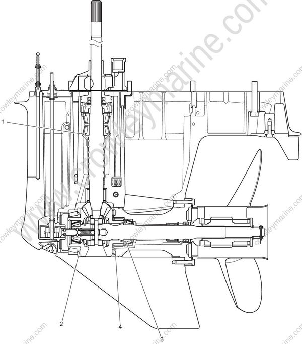
1.Pinion gear back-up shim
2.Front gear back-up shim
3.Propeller shaft thrust shim
4.Rear gear back-up shim
Front Gear Shim / Pinion Gear Shim
Follow the procedure below to adjust the front gear and pinion gear.
Adjusting front gear shim / pinion gear shim
- Install standard thickness of pinion gear back-up shim first, thickness must be modified according to ± design specification mark on the gear.
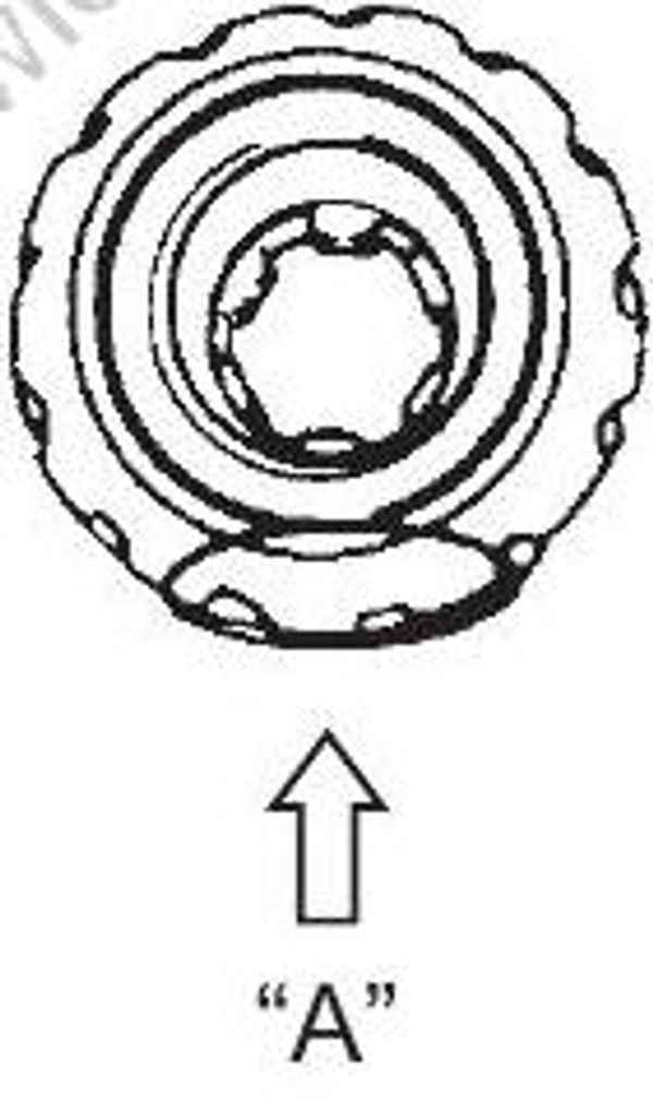
“A”: ± design spec. mark
- To obtain the initial thickness of the front gear back up shim, calculate the driveshaft thrust play according to the following procedure.
a) Place the front gear and front gear bearing, and then driveshaft, pinion gear, pinion back-up shim and driveshaft bearing spacer into gearcase.
Do not install the front gear back-up shim at this time.
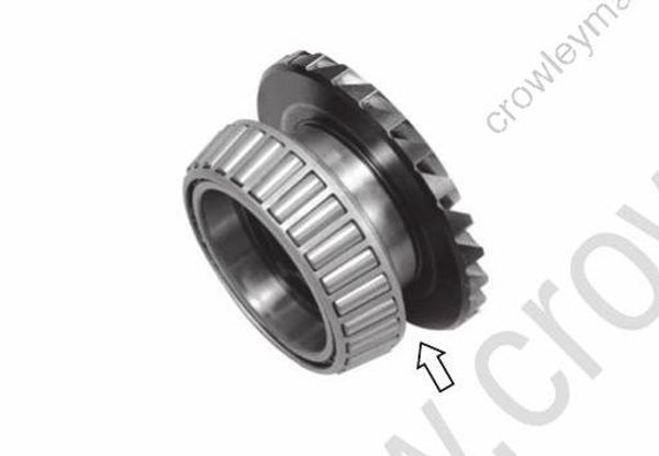
b) Measure the depth from the top surface of gearcase to the bearing spacer.
Designate this measurement as “A”.
Special tool
(A): 09900–20101 (Vernier calipers (150 mm))
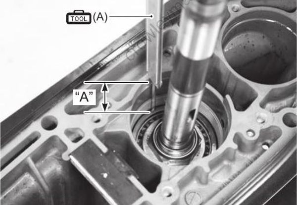
The front gear back-up shim is temporary so that any of the shims, such as a standard one, can be used.
c) Assemble the front gear, back-up shim and front gear bearing.
As the same way as procedure (a), place each parts into gearcase.
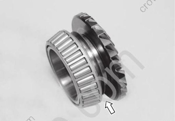
d) Measure the depth from the top surface of gearcase to the bearing spacer.
Designate this measurement as “B”.
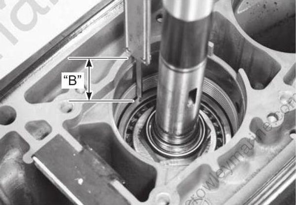
e) Calculate the driveshaft thrust play by the following formula.
Driveshaft thrust play = measurement “A” – measurement “B”
Driveshaft thrust play specification
0.25 – 0.45 mm (0.01 – 0.018 in.)
- Select the initial thickness of the front gear back-up shim to be the thrust play reaches to the specified value.
Checking and adjusting tooth contact pattern
After obtaining the initial front gear back-up shim, check tooth contact pattern by the following procedure:
Before installing front gear, to assess tooth contact, apply a light coat of Prussian Blue on the convex surface of front gear.
Correctly assemble driveshaft oil seal housing, driveshaft, front gear, pinion gear and related components.
Refer to “Lower Unit Assembly” (Page 3C-18). Do not install rear gear at this time.Tighten pinion nut to specified torque.
Tightening torque
Pinion nut: 145 N•m (14.5 kgf•m, 105.0 lbf•ft)
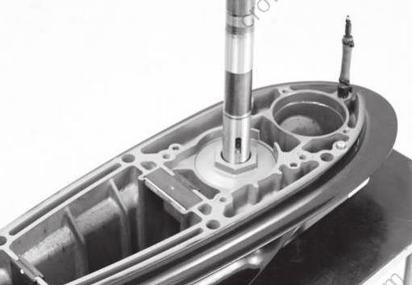
- Place the special tool to propeller shaft as shown in the figure.
Special tool
(A): 09951–09310 (Gear adjust spring set)
• Use shorter spring (free length: 23.8 mm, 0.94 in) in the gear adjust spring set to check the tooth contact pattern.
• Before installing special tool, move shifter dog to rear gear position.
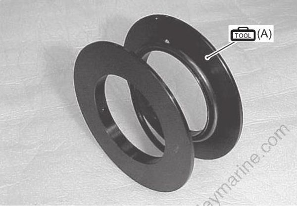
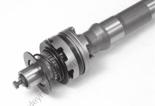
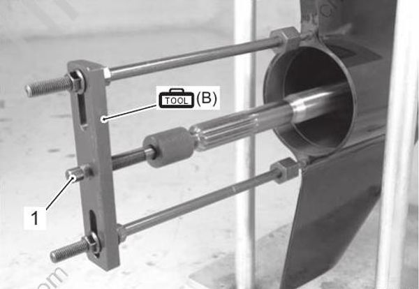
Install propeller shaft into gearcase.
Install special tool into gearcase and attach them to the propeller shaft as shown in the illustration.
Special tool
(B): 09951–99310 (Gear holder)
- Turning bolt (1) clockwise to push front gear inward, tighten lightly the bolt (1) after having stopped.
Tightening torque: approx. 5 N•m (0.5 kgf•m)
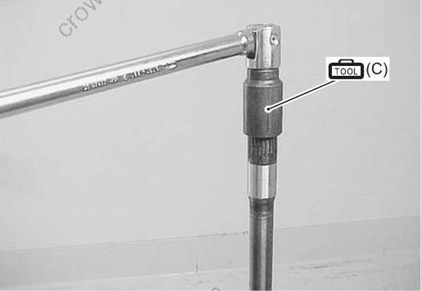
- Using the driveshaft holder tool, rotate the driveshaft 5 – 6 times.
Special tool
(C): 09921–29410 (Driveshaft holder)
- Carefully pull out propeller shaft to check tooth contact pattern.
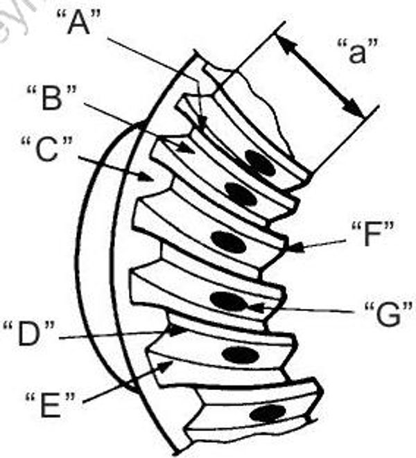
“A”:Concave side
“B”:Convex side
“C”:Heel
“D”:Tooth top
“E”Tooth bottom
“F”Toe
“G”Tooth contact pattern
“a”:Tooth width
Optimum tooth contact
The optimum tooth contact is shown in the figure.
A shim adjustment may be necessary to obtain this contact pattern.
Driveshaft thrust play should be checked when increasing or decreasing shim thickness to adjust tooth contact.
Optimum tooth contact
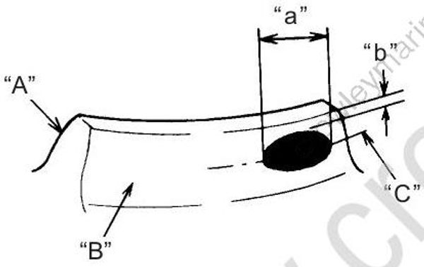
“A”:Heel
“B”:Convex side
“C”:Toe
“a”:Approx. 1/3 of tooth width
“b”:Approx. 1 mm (0.04 in)
Example [A]
Incorrect topside toe contact:
Correction measures:
- Decrease thickness of front gear shim.
- Slightly decrease pinion gear shim thickness.
Setting the tooth contact in the top side toe contact may cause damage and chipping on front and pinion gears. Do not set the tooth contact as such top side toe contact.
Example of incorrect
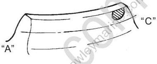
“A”: Heel
“C”: Toe
Example [B]
Incorrect bottom side toe contact:
Correction measures:
- Increase thickness of front gear shim.
- Slightly increase pinion gear shim thickness.
Setting the tooth contact in the bottom side toe contact may cause chipping on pinion gear. Do not set the tooth contact as such bottom side toe contact.
Example of incorrect
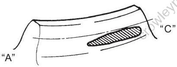
“A”: Heel
“C”: Toe
Rear Gear Shim
After adjusting the front gear tooth contact pattern, follow the procedure below to adjust the rear gear.
- To obtain the initial thickness of the rear gear back up shim, calculate the driveshaft thrust play according to the following procedure.
a) Place the front gear and front gear bearing, and then driveshaft, pinion gear, pinion back-up shim and driveshaft bearing spacer into gearcase.
Do not install the front gear back-up shim at this time.
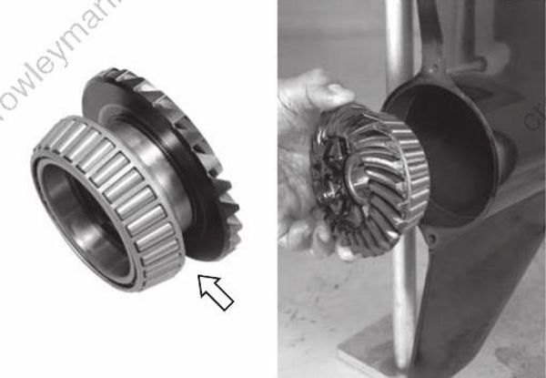
b) Correctly assemble rear gear, rear gear thrust bearing, rear gear thrust washer, propeller shaft, propeller shaft bearing housing and related components.
Do not install the rear gear back-up shim at this time.
Tighten both housing retaining bolts to the specified torque.
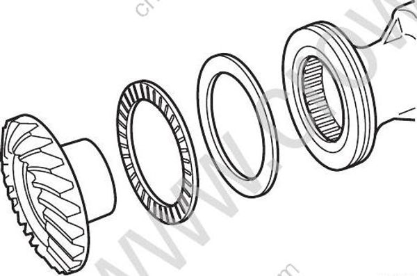
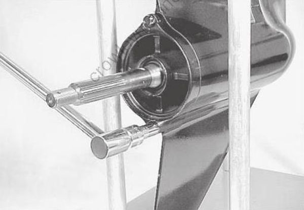
c) Measure the depth from the top surface of gearcase to the bearing spacer.
Designate this measurement as “A”.
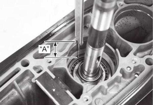
The rear gear back-up shim is temporary so that any of the shims, such as a standard one, can be used.
d) Assemble the rear gear, back up shim and rear gear bearing.
As the same way as procedure (b), place each parts into gearcase.
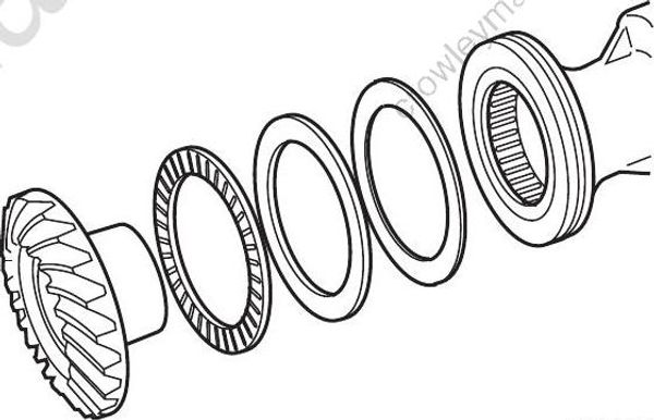
e) Measure the depth from the top surface of gearcase to the bearing spacer.
Designate this measurement as “B”.
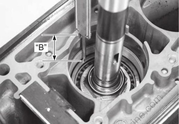
f) Calculate the driveshaft thrust play by the following formula.
Driveshaft thrust play = measurement “A” – measurement “B”
Driveshaft thrust play specification
0.25 – 0.45 mm (0.01 – 0.018 in.)
- Select the initial thickness of the rear gear back-up shim to be the thrust play reaches to the specified value.
Checking and adjusting tooth contact pattern
After obtaining the initial rear gear back-up shim, check tooth contact pattern by the following procedure:
Before installing rear gear, to assess tooth contact, apply a light coat of Prussian Blue on the convex surface of rear gear.
Correctly assemble driveshaft oil seal housing, driveshaft, front gear, pinion gear and related components.
Refer to “Lower Unit Assembly” (Page 3C-18).Tighten pinion nut to specified torque.
Tightening torque
Pinion nut: 145 N•m (14.5 kgf•m, 105.0 lbf•ft)
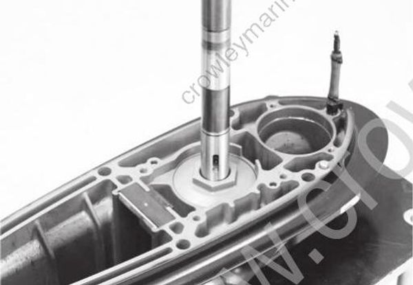
- Correctly assemble rear gear, rear gear bearing, propeller shaft, propeller shaft thrust bearing, propeller shaft bearing housing and related components.
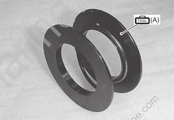
When assemble the rear gear and propeller shaft housing assembly, place the special tool between clutch dog shifter and rear gear as shown in the figure.
• Use shorter spring (free length: 23.8 mm, 0.94 in) in the gear adjust spring set and install it between rear gear and clutch dog to check the tooth contact pattern.
• Before installing special tool, move shifter dog to front position.
Special tool
(A): 09951–09310 (Gear adjust spring set)
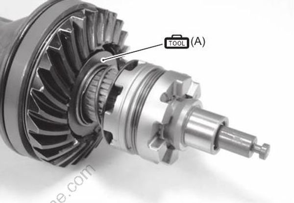
- Install rear gear and propeller shaft housing assembly into gearcase, then tighten both bearing housing retaining bolts to specified torque.
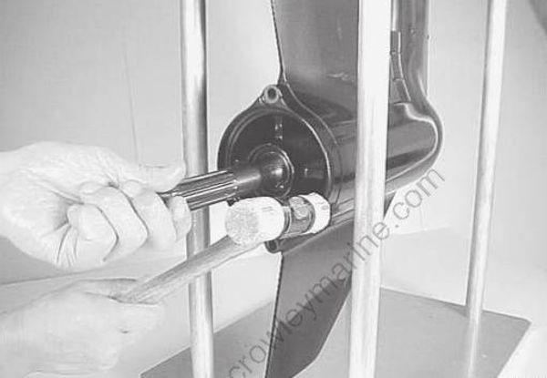
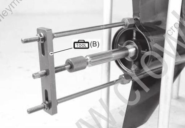
- Remove two bearing housing retaining bolts, then screw long bolts of special tool to secure the bearing housing.
Special tool
(B): 09951–99310 (Gear holder)
Install the special tool and then attach it to the propeller shaft as shown.
Turning bolt (1) counterclockwise to pull rear gear outward, tighten lightly the bolt (1) after having stopped.
Tightening torque: approx. 5 N•m (0.5 kgf•m)
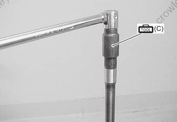
- Using the driveshaft holder tool, rotate the driveshaft 5 – 6 times.
Special tool
(C): 09921–29410 (Driveshaft holder)
- Carefully pull out the propeller shaft and housing to check the tooth contact pattern.
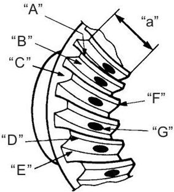
“A”:Concave side
“B”:Convex side
“C”:Heel
“D”:Tooth top
“E”Tooth bottom
“F”Toe
“G”Tooth contact pattern
“a”:Tooth width
Optimum tooth contact
The optimum tooth contact is shown in the figure.
A shim adjustment may be necessary to obtain this contact pattern.
Optimum tooth contact
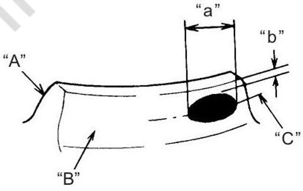
“A”: Heel
“B”: Convex side
“C”: Toe
“a”: Approx. 1/3 of tooth width
“b”: Approx. 1 mm (0.04 in)
Example [A]
Incorrect topside toe contact:
Correction measures:
- Decrease thickness of rear gear shim.
- Slightly decrease pinion gear shim thickness.
Setting the tooth contact in the top side toe contact may cause damage and chipping on rear and pinion gears. Do not set the tooth contact as such top side toe contact.
Example of incorrect
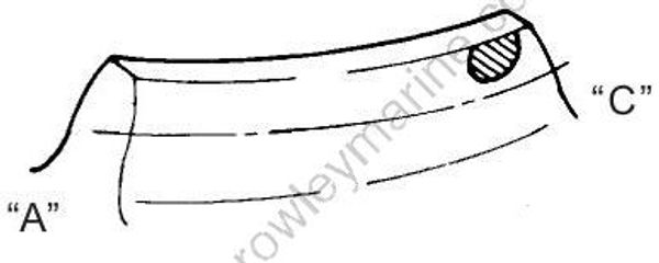
“A”: Heel
“C”: Toe
Example [B]
Incorrect bottom side toe contact:
Correction measures:
- Increase thickness of rear gear shim.
- Slightly increase pinion gear shim thickness.
Setting the tooth contact in the bottom side toe contact may cause chipping on pinion gear. Do not set the tooth contact as such bottom side toe contact.
Example of incorrect
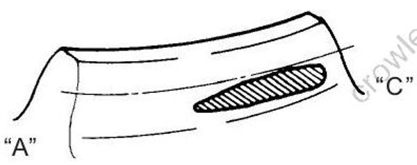
Propeller Shaft Thrust Shim Adjustment
The thickness of appropriate shim must be selected by the following method.
Correctly assemble the lower unit without the propeller shaft thrust shim on the propeller shaft.
Assemble gear adjusting gauge to the propeller shaft.
Special tool
(A): 09951–09530 (Gear adjusting gauge)
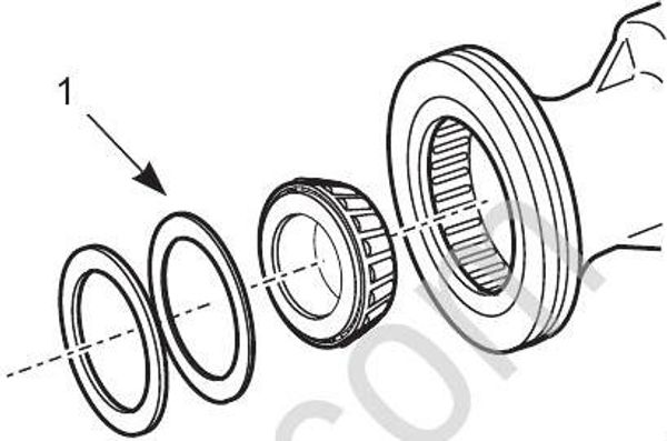
- Propeller shaft thrust shim
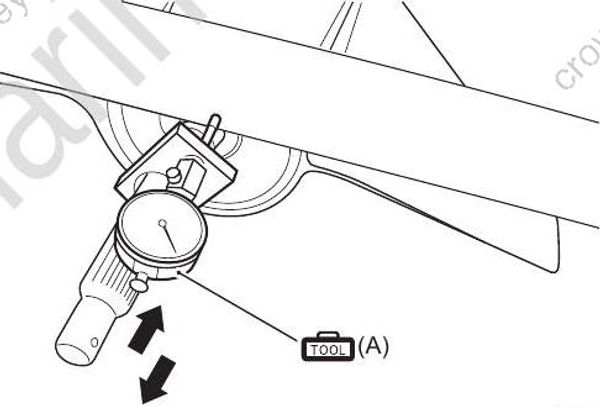
Push propeller shaft inward.
Hold shaft in and set dial gauge pointer to zero.
Slowly pull shaft outward and read the maximum thrust play on the dial gauge.
Designate this amount of play as “A”.Propeller shaft thrust play “A” must be known to adjust propeller shaft thrust shim.
The thickness of appropriate propeller shaft thrust shim is decided by the following calculating formula.
Appropriate propeller shaft thrust shim thickness = Thrust play (A) + 0.1 mm (0.004 in)
- Lower unit must be assembled by installing the propeller shaft thrust shim of the thickness decided by the calculating formula.
Checking Propeller Shaft Thrust Play
After adjusting all gear positions, measure the propeller shaft thrust play. If not within the following specification, a shim adjustment is required.
Use only the propeller shaft thrust shim to adjust thrust play.
Propeller shaft thrust play
0 mm (0 in.)
- Assemble the gear adjusting gauge to the propeller shaft.
Special tool
(A): 09951–09530 (Gear adjusting gauge)
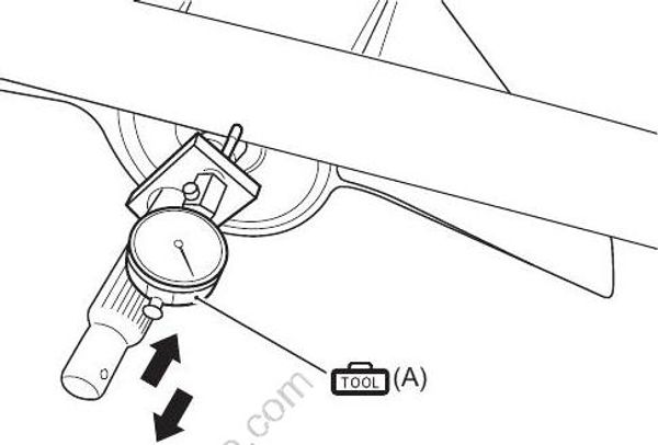
Push propeller shaft inward.
Hold the shaft in and set the dial gauge pointer to zero.
Slowly pull the shaft outward and read the maximum thrust play on the dial gauge.
If the measurement is more than the specification, increase the propeller shaft thrust shim thickness.
After checking the thrust play of propeller shaft, make sure that the propeller shaft can be rotated smoothly by hand in neutral. If it is not smoothly, readjust the propeller shaft thrust shim.
