

Precautions
Precaution for Power Trim and Tilt
Failure to take proper precaution when servicing a PTT unit can cause severe personal injury.
Be sure to take the following precautions when servicing the PTT system:
• During removal or installation of PTT unit, the engine must be firmly secured and its weight fully supported by the hoist.
• Before checking PTT fluid level, tilt the motor to the full-up position and engage the tilt lock lever.
• To prevent system malfunctions, ensure that all components are kept free from dirt or contamination.
• Reinstall all O-rings, seals, springs etc. with the component(s) to which they belong. This will prevent possible confusion and will ensure correct reassembly.
General Description
Power Trim and Tilt Description
- The power trim and tilt system components are an electric motor, a pump unit, a fluid reservoir and trim/tilt cylinders. The outboard can be trimmed “UP” or “DOWN” while under way, and can be tilted for beaching, operating in shallow water or trailering.
Trim and tilt “UP” or “DOWN” is obtained by supplying power to a permanent magnet type motor. This motor will rotate clockwise for “UP” or counterclockwise for “DOWN”, according to power delivered via the PTT relay, which is mounted on the electric part holder.
Power Trim and Tilt Hydraulic Diagram
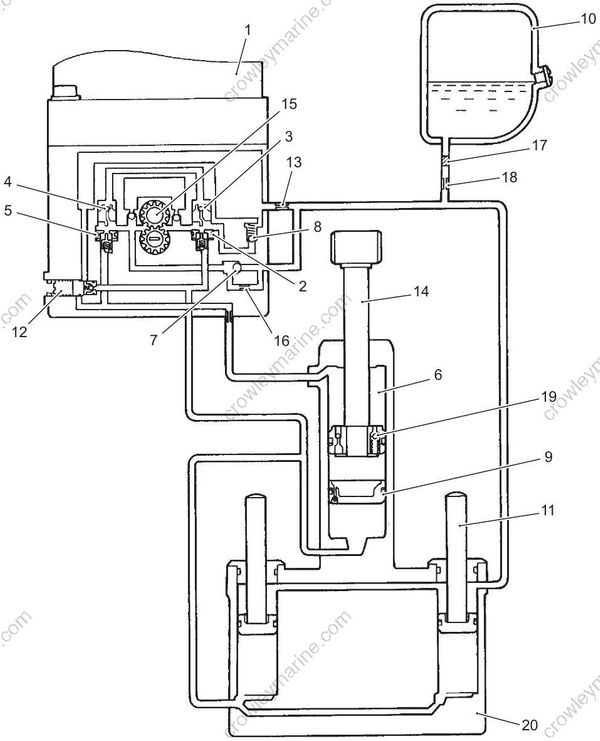
1.PTT motor
2.Up check valve
3.Up shuttle valve
4.Down shuttle valve
5.Down check valve
6.Tilt cylinder Upper chamber
7.Down relief check valve
8.Up relief valve
9.Free piston
10.Oil reservoir
11.Trim rod
12.Manual release valve
13.Pump room orifice
14.Tilt rod
15.Gear pump
16.Down relief orifice
17.Filter
18.Tank room orifice
19.Impact relief valve
20.Cylinder body
Principles of Power Trim and Tilt Operation Description
By motor operation, the geared pump will be driven, and by turning the motor to the right or to the left, oil flow will change its direction. This causes “UP” and “DOWN” movements of the piston rod of the tilt cylinder and the trim rod of the trim cylinder.
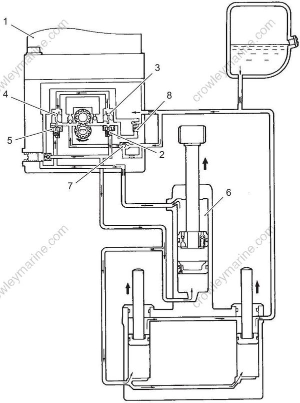
Trim / Tilt Up Circuit
- When the PTT switch is operated “UP” position, the electric motor and gear pump (1) will operation on clockwise direction.
- Pressurized oil will open “Up” check valve (2) and the oil will flow through “Up” shuttle valve (3) to the “Down” shuttle valve (4). Following operation of valve (4), “Down” check valve (5) will open mechanically.
- Pressurized oil flows through the “Up” check valve (2) to the bottom of the trim and tilt cylinders, thereby pushing the trim and tilt pistons upward.
- Residual oil in the upper area of the tilt cylinder (6) is returned to the pump through “Down” check valve (5).
- Any oil in the area above both trim cylinder pistons will be returned to the reservoir.
- Oil will then flow from the reservoir to the pump to stabilize the balance of the oil volumes.
- When the engine is fully tilted up, oil pressure will correspondingly increase in the lower chamber of the tilt and trim cylinders. But, to protect the PTT unit from excessively high pump pressure, the “Up” relief valve (8) begins to open.
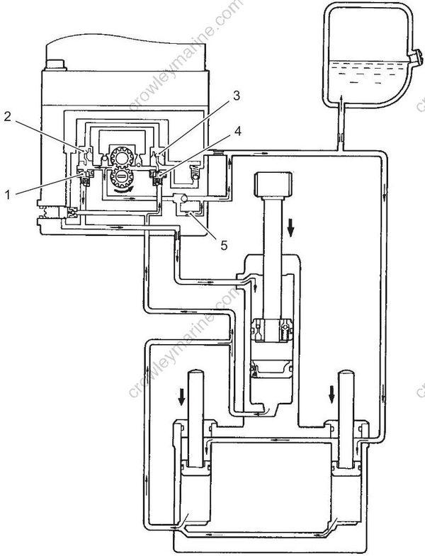
Trim / Tilt Down Circuit
- When the PTT switch is operated in the “DOWN” position, the electric motor will rotate in a counterclockwise direction and turn the gear pump.
- The oil pressure will open the “Down” check valve (1) and oil will be forced through the “Down” shuttle valve (2). When the oil reaches “Up” shuttle valve (3), the “Up check valve (4) will begin to open mechanically.
- The pressurized oil flows through “Down” check valve (1) and then enters the upper area of the tilt cylinder. This thereby forces the tilt rod piston downward.
- When the swivel bracket contacts the trim rams, this pressure forces the trim pistons downward and oil from the reservoir is then able to enter the area above both trim rod pistons.
- Oil from the lower area of the trim and tilt cylinders now returns to the pump through “Up” check valve (4).
- Throughout the tilt action operation range, there is a difference in oil volume between the upper and lower chambers of the tilt cylinder, and any surplus oil is therefore directed to the reservoir by means of the “Down” relief orifice (5).
- Throughout trim operation range, oil will be discharged from the bottom of all three cylinders and the pump will only supply oil to the tilt cylinder. Excess oil is then vented to the reservoir through the “Down” relief orifice (5).
- To prevent damage from excessive oil pressure when all three rods are fully retraced, this pressure is relieved through the “Down” relief orifice (5).
Shock Absorber Circuit
This incorporated safety feature is for protection of the gearcase and prevention of internal PTT pressure build-up in the event of an impact.
- The pressure from a sudden impact will make impact relief valve (1) open, allowing oil from the upper area of the tilt cylinder to flow into the area between the tilt rod piston and the free piston. The tilt rod will then extend.
- When the moment of impact has passed, the PTT DOWN switch must be activated to return the engine to within the normal trim range. When the switch is pressed, the oil between the piston and free piston will be directed to the cylinder upper chamber via the return valve below the tilt piston.
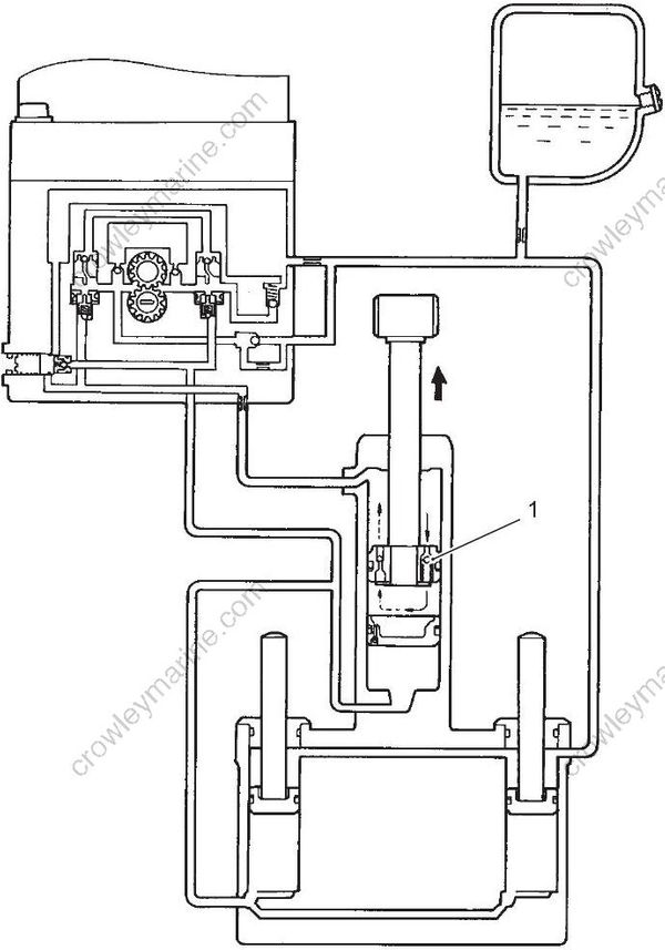
Manual Release Circuit (Down Mode)
- By opening the manual release valve (1), the engine can be lowered manually to a running position. Oil underneath the trim and tilt pistons will be directed through this valve into the area above the tilt rod piston.
- The volume of oil flowing from under the trim rod pistons will be larger than the area above the tilt rod piston can accommodate. Excess oil therefore returns through the manual release valve (1) to the reservoir.
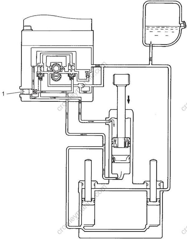
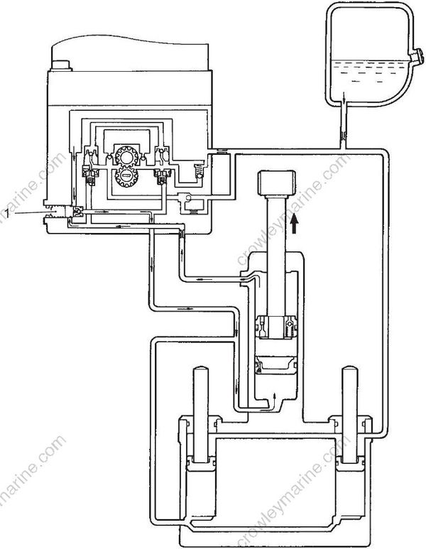
Manual Release Circuit (Up Mode)
- With the manual release valve (1) open, the engine can also be raised manually to the fully tilted position.
- Oil from the upper chamber of the tilt cylinder will flow through valve (1) into the lower chamber of the cylinder.
- The upward movement of the piston rod will increase the cylinder area beneath it, thereby allowing oil from the reservoir to flow into this area.
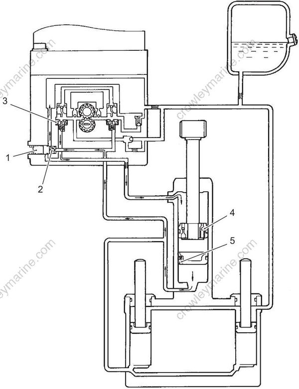
Tilt System Pressure Relief
- If engine speed exceeds approx. 1500 r/min when operating in shallow water drive mode, oil pressure will increase underneath the tilt piston. The relief valve (2) (incorporated in the manual release valve (1)) will then open.
- The oil below the tilt piston will then flow to the reservoir through the relief valve (2).
- As the power of the engine continues to exert downward force on the tilt piston, this will open “Down” check valve (3), thereby allowing oil from the reservoir to flow into the chamber above the tilt piston.
- In this way, high internal pressure is relieved and the engine will slowly tilt downward until it reaches the highest position in the Trim range.
Thermal Expansion Relief
- High ambient temperature will, through thermal expansion, induce a build-up of oil pressure inside the PTT unit.
- Expansion of the oil and the resulting high pressure will open the relief valve (2), thereby providing unit protection by directing oil back to the reservoir.
Expanded oil in the tilt cylinder upper chamber will return to reservoir passing through impact relief valve (4) → free piston check valve (5) → thermal relief valve (2).
Schematic and Routing Diagram
Power Trim and Tilt System Diagram
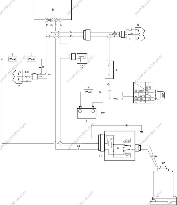
1.Battery
2.30 A fuse
3.Main switch
4.Switch panel
5.PTT switch (remote control box)
6.ECM
7.PTT switch (side cover)
8.10 A fuse
9.Main fuse 60 A
10.Tilt limit switch
11.PTT motor relay
12.PTT motor
PTT System Operation
The PTT relay is controlled by the ECM.
The ON/OFF signal for the PTT UP or DOWN is inputted to the ECM PTT relay drive circuit. The input signal is sending from ECM terminals No.16 or 22 and the output signal from terminals No.83 or 82, and they control ON/ OFF for PTT relay's UP or Down circuit.
For the motor trim/tilt UP or DOWN by the PTT relay control circuit in ECM, the battery power must be supplied to ECM with the sub battery cable connected to the main wiring harness.
Even through any PTT switch is depressed with only the main battery cable connected on these models, the PTT motor will not be operated.
– When the PTT switch located on the side cover is operated, the following operation takes place:
With the main switch is in OFF position, and the PTT switch is operated, the tilt/trim will be operated.
With the above mentioned condition, operating the PTT switch will supply a 12 V power to the ECM.
When this signal is received, the ECM operates the main relay is in ON, allowing the ECM drive signal to feedback to the ECM and the PTT relay circuit.
Thus the PTT system functions if the PTT switch located on the side cover is operated.
When the PTT switch signal turns from ON to OFF and a predetermined time has elapsed, the ECM drive voltage will be interrupted automatically.
– To operate the trim/tilt to move UP/DOWN by operating the PTT switches that are located on the switch panel and the remote control box, it is necessary to turn the main switch ON.
The reason for this is that 12 V power will not be supplied to the PTT switch without turning the main switch ON.
• When an engine position (port, center, or starboard) is registered to BCM during initial setting of SPC system, the input voltages from PTT switch to ECM terminals No.16 (Lbl) and No.22 (P) are required.
• The output voltages from No.82 (P) and No.83 (Lbl) of ECM are PTT motor relay control signals to tilt/trim down or trim/tilt up the outboard motor.
Diagnostic Information and Procedures
Diagnose PTT System Malfunction
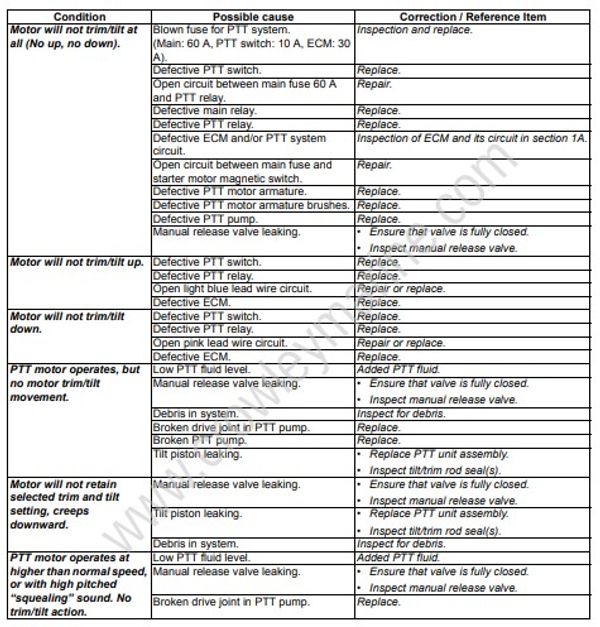
Service Instructions
Checking PTT Fluid Level
- Raise the engine to a full-tilt up position.
- Lower the manual tilt lock lever (1).
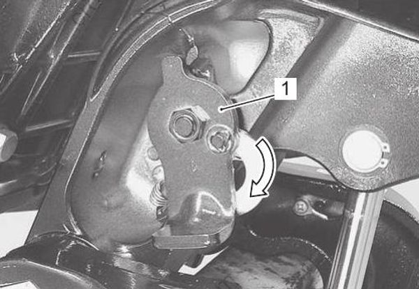
- Remove the oil filler plug (2).
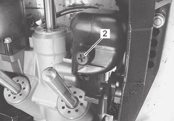
- If oil can be seen at filler plug level, the reservoir is full.
If fluid level is low, refill with the recommended PTT fluid.
Mixing of different fluids may cause chemical reaction and deterioration.
To ensure consistent pump operation, never mix different types of PTT fluid.
Recommended PTT fluid
• 99000-22810 (PTT Fluid (1 Liter))
• Dexron III automatic transmission fluid or equivalent
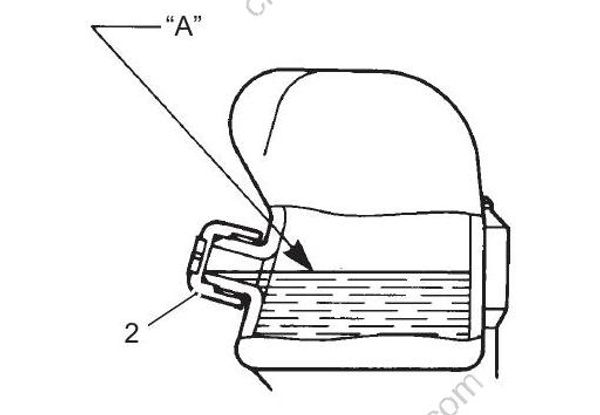
“A”: Oil level (when full tilted)
- Reinstall oil filler plug (2).
Air Bleeding from PTT Unit
- Check that the manual release valve (1) is tightened to the specified torque.
Do not over tighten manual release valve.
Tightening torque
Manual release valve (a): 3.5 N·m (0.35 kgf-m, 2.5 lbf-ft)
Direction of rotation
Counterclockwise: Open
Clockwise: Close
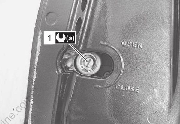
- Operate the PTT switch, raising and lowering the motor up and down (full tilt position to full trim down position) 4 to 5 times.
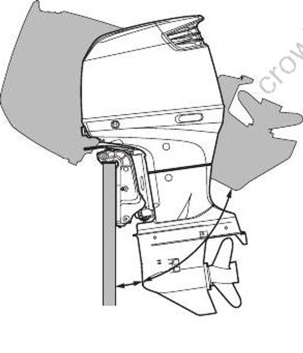
- Check PTT fluid level, topping off if necessary.
- Reinstall oil filler plug.
Setting Trim Down Position Limit
Once the ECM has been replaced or the trim sensor removed and reinstalled, the resetting of the trim down position limit should be performed.
Perform this set-up after the current position setting has been cancelled, as explained in the following procedure.
The tilt upper limit should be adjusted by the tilt limit cam (switch).
Canceling The Trim Down Position Limit Setting
- Turn the main switch to the “ON” position.
- Pull out the emergency stop switch lock plate.
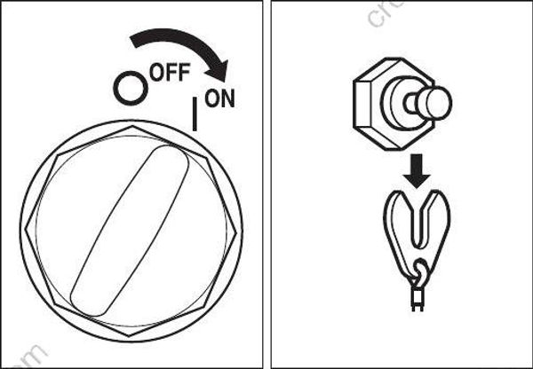
- Make sure that remote control handle is in “NEUTRAL”.
- Confirm the select switch LED lights, if not, depress the select button on the switch panel.
Depress the “THROTTLE ONLY” button.
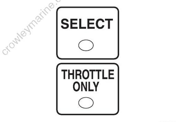
- Move the control handle forward until the caution buzzer sounds one time.
At this time, the message of “Set Limit Angle” will appear on the gauge screen.
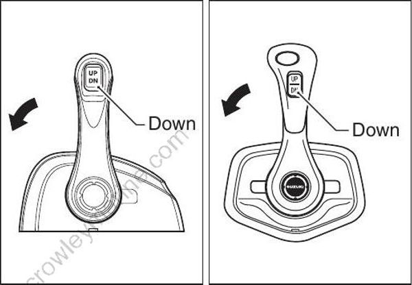
- Press the “DOWN” side of PTT switch for three seconds and the buzzer will sound twice briefly indicating the setting has been canceled.
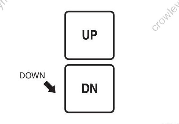
- Return the throttle to the fully closed position. At this time, “Set Limit Angle” indication will be cleared.
Setting The Trim Down Position Limit
Make sure that main switch is ON.
Press the “DOWN” or “UP” side of the PTT switch so that the optimum full trim down position for the boat can be obtained.
Pull out the emergency stop switch lock plate.
Make sure that remote control handle is in “Neutral”. (Check that the neutral switch is in the “ON” position.)
Confirm the throttle only LED lights.
Move the control handle forward until the caution buzzer sound one time.
Press the “DOWN” side of the PTT switch three times within three seconds. The buzzer will sound one time briefly indicating the setting has been accepted.
Return the throttle to the fully closed position and install the lock plate on the emergency switch.
Operate the full tilt up and full trim down operations several times by pressing the PTT switch and check that the setting of the down limit is properly set.
Power Trim and Tilt Unit Removal and Installation
Removal
Remove the lower side covers.
Refer to “Lower Side Cover Removal and Installation” in Section 2A (Page 2A-3).
Raise the engine to the full tilt up position and lower the manual tilt lock lever (1).
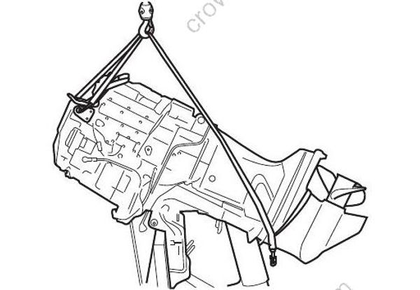
Failure to take proper precaution when servicing a PTT unit can cause severe personal injury.
During the removal or installation of PTT unit, the engine must be firmly secured and its weight fully supported by the hoist. (See below).
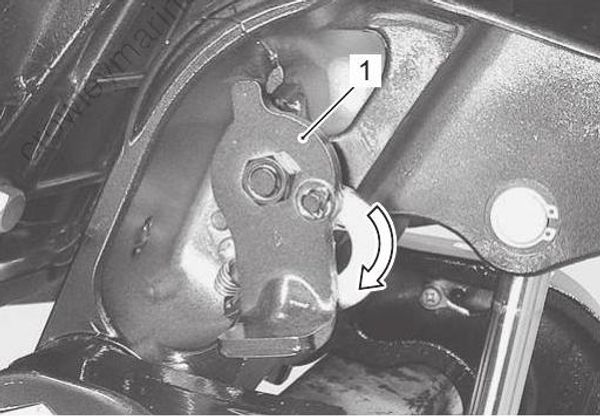
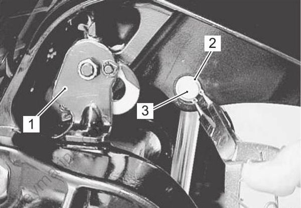
- Remove the tilt rod snap ring (2) and push the tilt rod upper shaft pin (3) out.
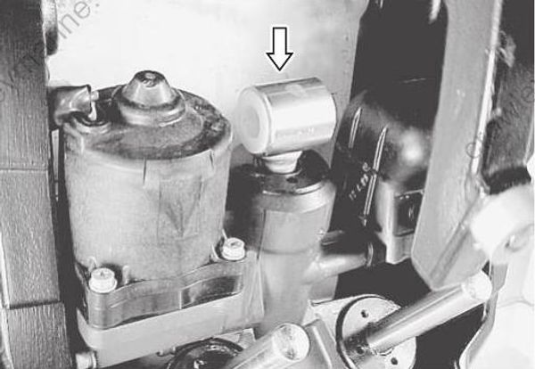
- Lower the tilt rod to the full down position and disconnect the battery cable.
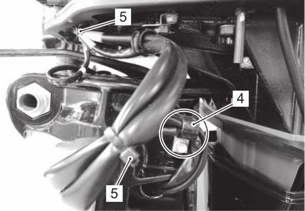
- Remove the clamp (4) and cut the cable tie (5) binding PTT motor cable and trim sensor lead.
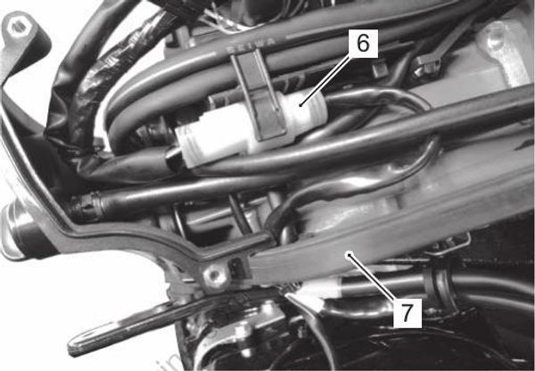
Disconnect the PTT motor cable lead wire connector (6).
Remove the PTT motor cable from side cover seal (7).
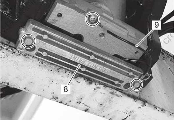
- Remove two bolts and anode (8). Remove the screw securing bonding wire (9).
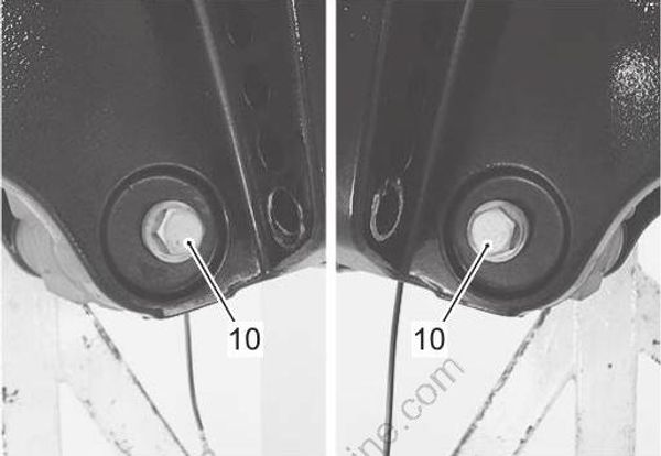
- Remove two bolts (10) securing PTT cylinder lower shaft to STBD/PORT clamp bracket.
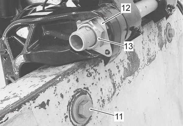
Remove two STBD motor mounting bolts (11).
Using flat screw-driver, drive locking edge of lock washer (12) to clamp bracket side.
Loosen the clamp bracket shaft nut (13).
Complete removal of the clamp bracket shaft nut is not required.
Nut should be loosened as far as the end of the shaft threads only to facilitate removal of the PTT unit.
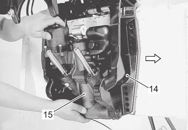
Slide the STBD clamp bracket (14) fully outward to the right hand side.
Remove the PTT unit (15) from between the clamp brackets.
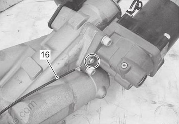
- Remove the bonding wire (16) from PTT unit.
Installation
Installation is reverse order of removal with special attention to the following steps.
- Lower tilt rod to full down position.
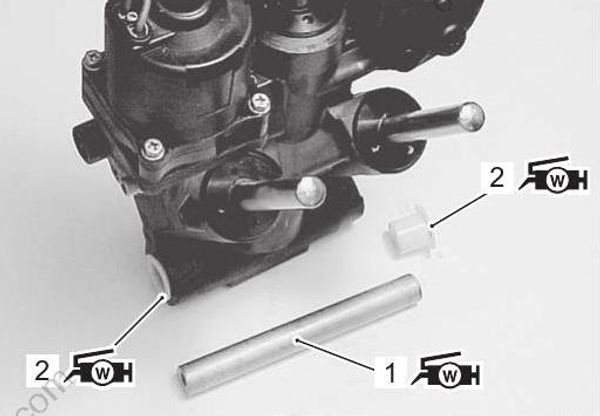
- Apply water resistant grease to the tilt cylinder lower shaft (1) and lower shaft bushings (2).
Install the lower shaft (1) and bushings (2) to PTT unit.
: Grease 99000–25350 (SUZUKI Water Resistant Grease EP2 (250 g))
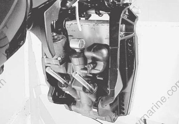
- Place the PTT unit (with lower shaft) in position between clamp brackets.
- Tighten the clamp bracket shaft nut (4) to specified torque.
Tightening torque
Clamp bracket shaft nut (a): 43 N·m (4.3 kgf-m, 31.0 lbf-ft)
- After tightening clamp bracket shaft nut (4) with specified torque, bend the lock washer (3) edge toward nut to secure nut.
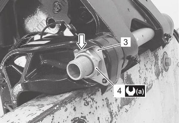
3. Washer
4. Nut
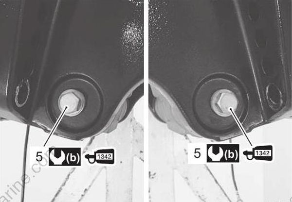
- Tighten two lower shaft bolts (5), pre-coated with thread lock, to specified torque.
: Thread lock cement 99000–32050 (SUZUKI Thread Lock 1342 (50 g))
Tightening torque
PTT cylinder lower shaft bolt (b): 60 N·m (6.0 kgf- m, 43.5 lbf-ft)
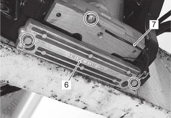
- Install anode (6) and bonding wire (7), then tighten bolts securely.
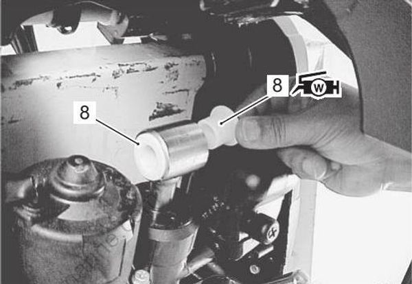
- Apply water resistant grease to tilt rod upper bushings (8), then install bushings in tilt rod.
Operate the PTT motor to extend the PTT rod upward. Align the tilt rod with the hole in the swivel bracket as the tilt rod extends.
: Grease 99000–25350 (SUZUKI Water Resistant Grease EP2 (250 g))
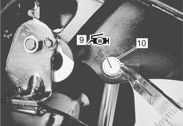
Apply water resistant grease to the tilt rod upper shaft pin (9), then insert the shaft pin through the swivel bracket and tilt rod.
Secure the upper shaft with the snap ring (10).
: Grease 99000–25350 (SUZUKI Water Resistant Grease EP2 (250 g))
Route the PTT motor cable properly through the side cover seal and connect the PTT cable connector.
Refer to “Wiring Harness Routing Diagram” in Section 4A (Page 4A-4).
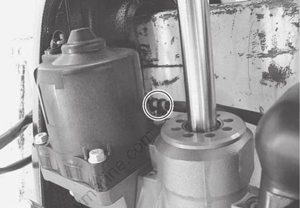
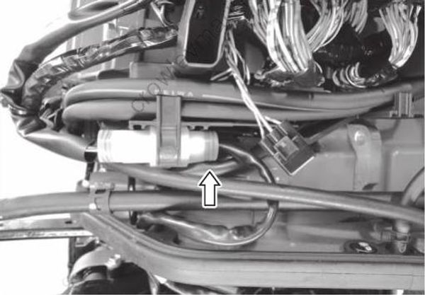
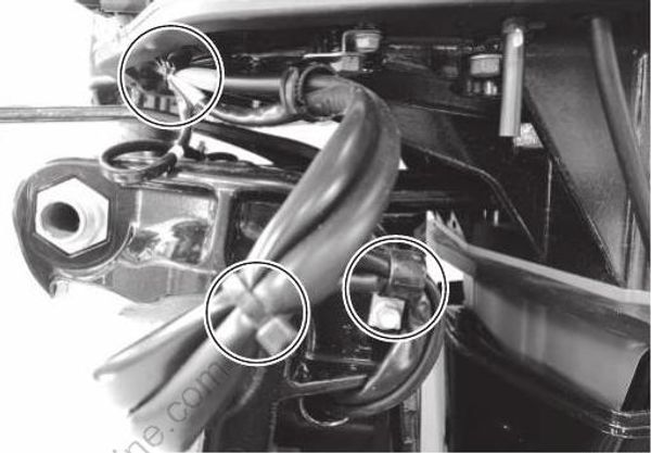
Power Trim and Tilt Unit Components
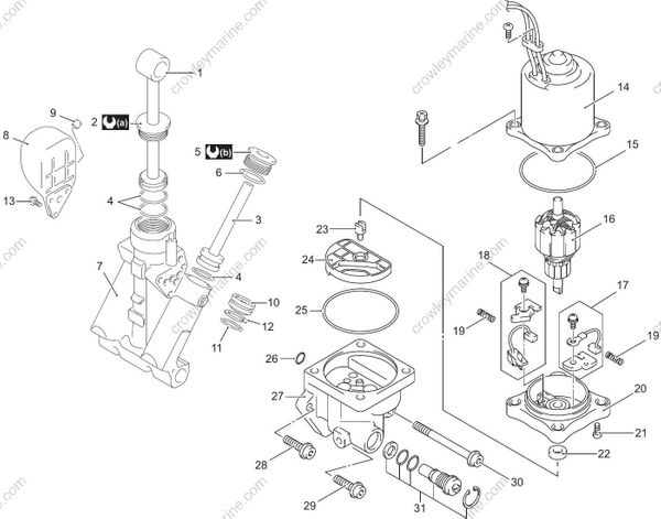

Power Trim and Tilt Unit Disassembly
Before disassembly, wash the PTT body with a stiff bristle brush and hot, soapy water to remove sand or dirt. Dry the PTT body with compressed air.
Place the lower section of the PTT unit in a vise.
Tighten the vise only enough to secure the PTT unit, DO NOT OVER TIGHTEN.
To prevent damage to the PTT cylinder use wood blocks, vise jaw protectors, etc., between the vise jaws and PTT components before tightening vise.
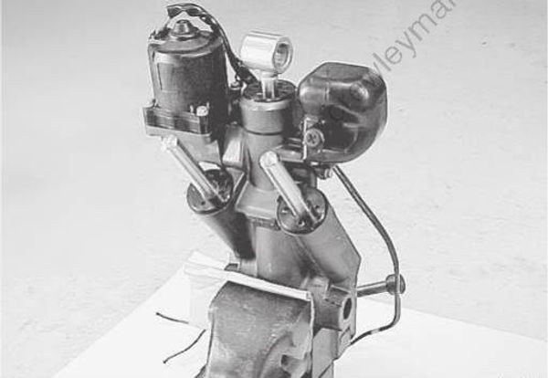
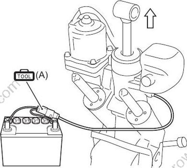
- Connect the PTT cable extension to PTT motor cable connector.
Special tool
[TOOL] (A): 09945–79310 (PTT cable extension)
- Connect the PTT cable extension leads (G, Bl) to battery and operate PTT motor until tilt rod is at maximum stroke (full-tilt up position). Unscrew the filler plug and drain PTT oil into a suitable container.
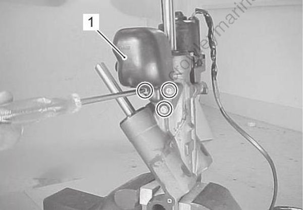
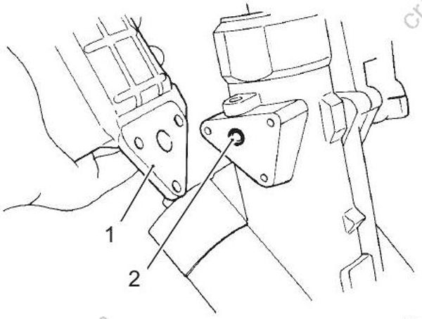
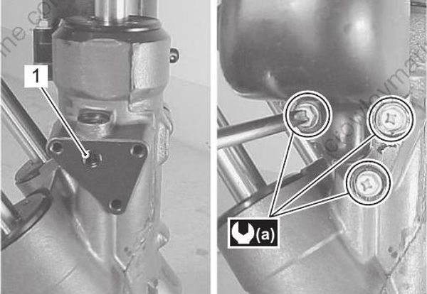
- Remove the three screws securing reservoir (1), then detach the reservoir (1) from cylinder body. Note the position of O-ring (2) and remove it.
Remove the PTT motor assembly (3).
Refer to “Power Trim and Tilt Motor Removal and Installation” (Page 2B-25).
Note the position of drive joint (4) and O-ring (5), before removing them.
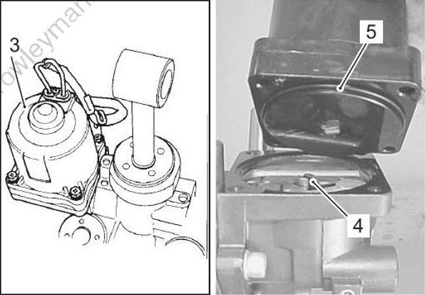
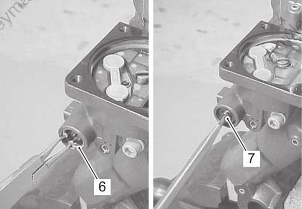
- Remove the manual release valve snap ring (6), then unscrew the manual release valve (7).
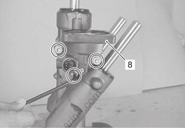
Remove the three bolts securing the PTT pump assembly (8), then detach the PTT pump assembly from PTT cylinder body.
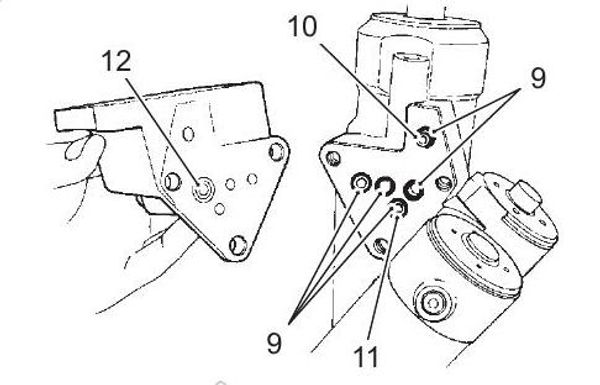
Note the position of O-rings (9), orifice collar (with ball valve) (10), orifice collar (with filter and ball valve) (12) and orifice collar (11), before removing them.
- Using special tool, unscrew the PTT cylinder head (13).
Special tool
[TOOL] (B): 09944–09820 (PTT cylinder cap tool)
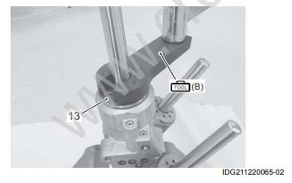
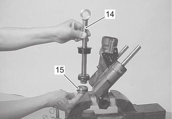
Pull the tilt rod/piston assembly (14) out of the tilt cylinder.
Remove the free piston (15) from the tilt cylinder.
Unscrew the piston retaining nut from the bottom of the tilt rod and remove the washer.
Carefully retain and account for four shock valves, each composed of spring, rod and ball.
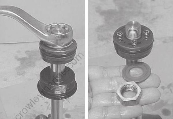
- Remove the piston assembly and PTT cylinder head from the tilt rod by sliding them down and off the rod end.
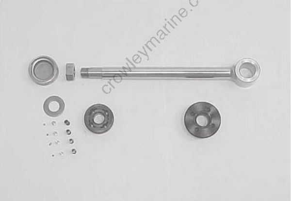
- Using special tool, unscrew the trim cylinder head.
Special tool
[TOOL] (C): 09944–09610 (PTT trim cap tool)
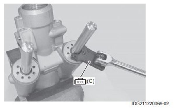
- Pull the trim rod/piston assembly out of the trim cylinder.
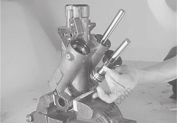
Power Trim and Tilt Unit Reassembly
Assembly is reverse order of disassembly with special attention to following steps.
• Do not reuse O-rings and seals once removed.
Always use new parts.
• Lubricate all components and O-rings with PTT fluid before assembly.
• Do not reuse PTT fluid, always refill with new fluid.
Tilt Rod
When tightening the piston retaining nut on the tilt rod piston, apply Thread lock 1342 to the threads.
Tighten the nut to specified torque.
: Thread lock cement 99000–32050 (SUZUKI Thread Lock 1342 (50 g))
Tightening torque
Piston retaining nut (a): 100 N·m (10.0 kgf-m, 72.5 lbf-ft)
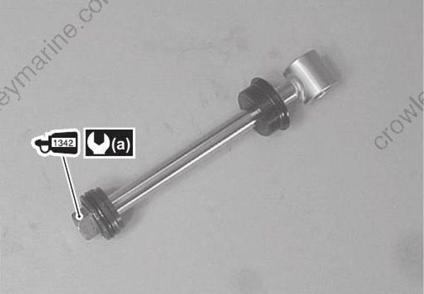
Installing Tilt Rod / Piston
- Pour 100 ml (3.4 oz) of PTT fluid into cylinder.
- Insert the free piston into cylinder and push it down to the bottom of the cylinder.
- Pour PTT fluid into the cylinder until it is topped off.
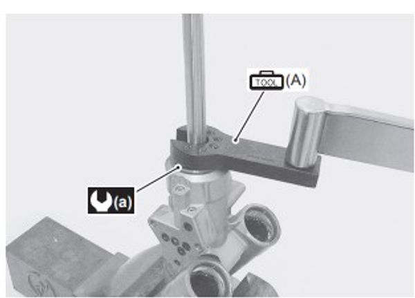
- Insert the tilt rod/piston into cylinder and thread the tilt cylinder head by hand until fully seated.
- Tighten the cylinder head to specified torque using special tool.
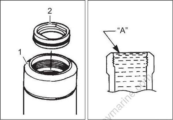
- Cylinder
- Free piston
“A”: Top OFF
Tightening torque
Tilt cylinder head (a): 210 N·m (21.0 kgf-m, 152.0 lbf-ft)
Special tool
[TOOL] (A): 09944–09820 (PTT cylinder cap tool)
Trim Rod
- Pour PTT fluid into the trim cylinder until it is topped off.
- Insert the trim rod/piston assembly into cylinder and thread the trim cylinder head by hand until fully seated.
- Tighten the trim cylinder head to specified torque using special tool.
Tightening torque
Trim cylinder head (a): 170 N·m (17.0 kgf-m, 123.0 lbf-ft)
Special tool
[TOOL] (B): 09944–09610 (PTT trim cap tool)
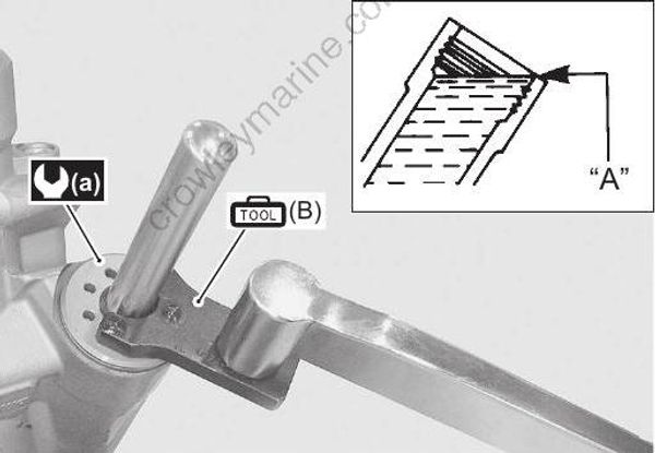
“A”: Upper edge
PTT Pump Assembly
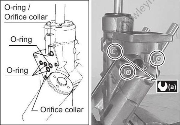
- Install five O-rings and orifice collars to PTT cylinder body.
Lubricate O-rings with PTT fluid before installing.
- Install PTT pump assembly, then tighten three screws to specified torque.
Tightening torque
PTT pump case screw (a): 8.5 N·m (0.85 kgf-m, 6.0 lbf-ft)
Manual Release Valve
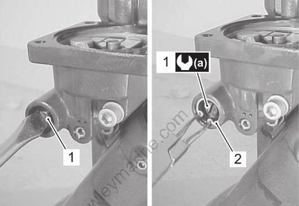
Oil and install the manual release valve (1).
Tighten the valve to specified torque.
Install snap ring (2).
Tightening torque
Manual release valve (a): 3.5 N·m (0.35 kgf-m, 2.5 lbf-ft)
PTT Motor
Install the PTT motor.
Refer to “Power Trim and Tilt Motor Removal and Installation” (Page 2B-25).
Reservoir
- Install O-ring (1) and reservoir, then tighten bolts to specified torque.
Tightening torque
Reservoir bolt (a): 5 N·m (0.5 kgf-m, 3.5 lbf-ft)
PTT Fluid
Pour recommended PTT fluid into reservoir to specified level.
Refer to “Checking PTT Fluid Level” (Page 2B-12).
Air Bleeding
Before installing the PTT unit on the outboard motor, use the following procedure to bleed air from the system.
- Support the PTT unit in an upright position in a vise.
- Fill the reservoir with PTT fluid to the specified level, then install oil filler plug.
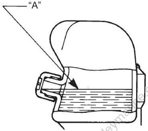
“A”: Oil level (When full-tilted)
- Tighten the manual release valve to the specified torque.
Tightening torque
Manual release valve: 3.5 N·m (0.35 kgf-m, 2.5 lbf-ft)
- Connect the PTT cable extension to the PTT motor cable connector.
Special tool
[TOOL] (A): 09945–79310 (PTT cable extension)
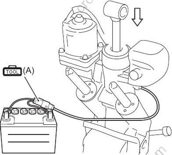
- Connect the two extension cable lead wires (G to positive/BI to negative) to the battery as shown in the illustration.
Operate the PTT motor until the PTT rod is in the fully trimmed down position (completely retracted). If the rod does not come down completely, push it in by hand while operating the motor.
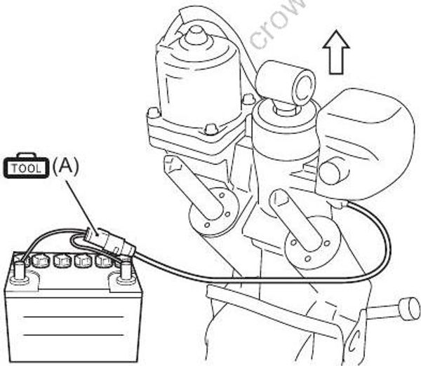
- Reverse the two extension cable lead wires (Bl to positive/G to negative). Operate the PTT motor until the PTT rod is in the full tilt up position (fully extended). If the rod does not come up completely, pull it up by hand while operating the motor.
- Remove the reservoir oil filler plug and fill with PTT fluid to the specified level.
- Repeat procedures 5 – 7 until the fluid level in the PTT unit stabilizes at the specified level.
Repeat the air bleeding procedure after the PTT unit has been installed on the outboard motor.
Refer to “Air Bleeding from PTT Unit” (Page 2B-12).
Power Trim and Tilt Unit Components Cleaning and Inspecting
Thoroughly wash all metal components with cleaning solvent and dry them with compressed air.
Arrange all components on a clean sheet of paper.
• Do not lay PTT components out on a rag, as dirt or lint may be transferred to these items which may cause possible system operating problems.
• If excessive wear, cracks, defective or other damage is found on any component, replace component.
• Inspect tilt rod and trim rod, replace if damaged or bent is found.
• Inspect the surface of tilt rod and trim rod for scores, grooves or roughness.
Slight roughness may be removed with fine emery paper.
A badly scored or grooved rod must be replaced.
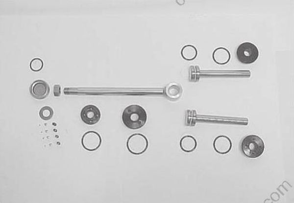
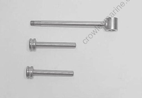
• Inspect the PTT cap seal and O-ring.
Replace if cuts, nicks, or excessive wear is found.
It is recommended that the O-ring always be replaced once the tilt/trim cylinder has been disassembled.
• Inspect the shock valves (spring, rod and ball).
Replace if there are any signs of rust or pitting.
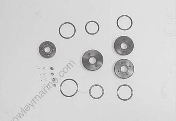
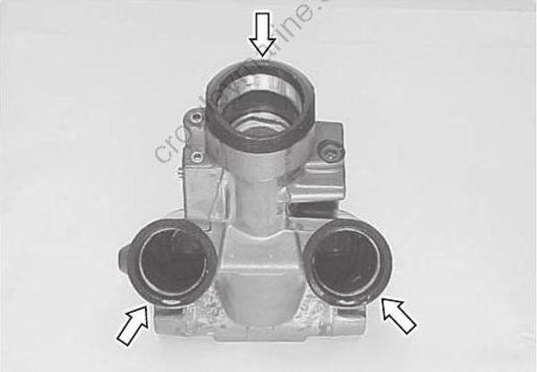
• Inspect the cylinder bore for evidence of a rough or grooved surface.
Light honing may rectify slight surface roughness or scarring, but a deeply scarred surface will require replacement of the tilt cylinder.
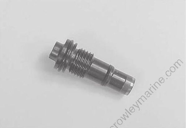
• Inspect manual release valve for damage.
Inspect manual release valve O-ring.
Replace if nicked or cut is found.
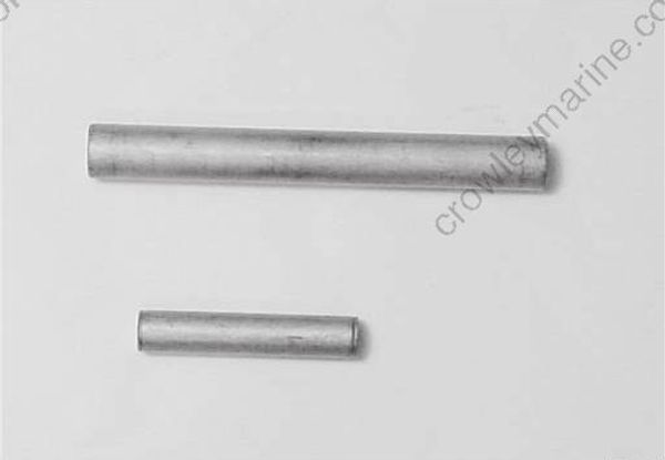
- Inspect lower rod.
If bending, cracks, corrosion or other damage is found, replace lower rod.
Inspect upper shaft for bent, twist or other damage.
Replace if necessary.
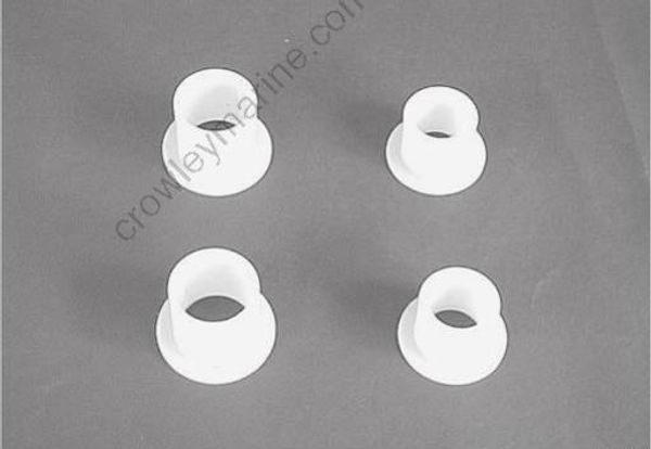
Inspect all bushings for excessive wear or other damage. Replace if necessary.
If bushing fit is loose when installing, replace bushing.
Power Trim and Tilt Motor Removal and Installation
Removal
Remove Power Trim and Tilt unit.
Refer to “Power Trim and Tilt Unit Removal and Installation” (Page 2B-14).
Before removing PTT motor, wash the PTT body with a stiff bristle brush and hot, soapy water to remove sand or dirt. Dry the PTT body with compressed air.
Place the lower section of the PTT unit in a vise.
Tighten the vise only enough to secure the PTT unit, DO NOT OVER TIGHTEN.
To prevent damage to the PTT cylinder use wood blocks, vise jaw protectors, etc., between the vise jaws and PTT components before tightening vise.
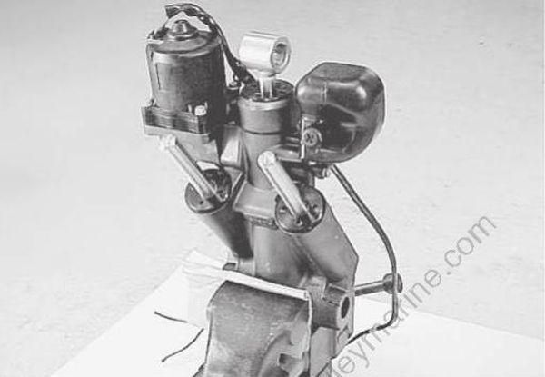
- Remove the four screws securing the PTT motor (1) to the PTT pump assembly.
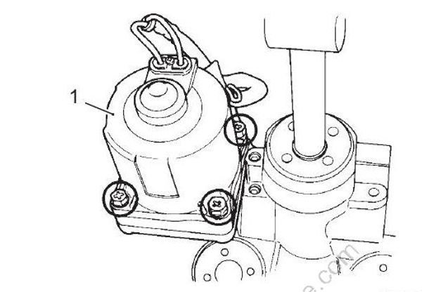
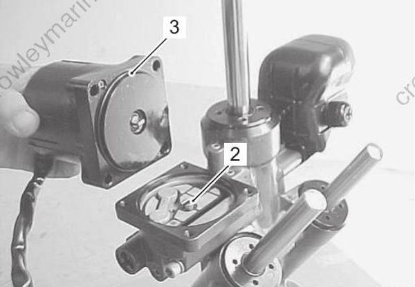
Detach the PTT motor from PTT pump assembly.
Note the position of drive joint (2) and O-ring (3) and remove them.
Installation
Installation is reverse of removal with special attention to following steps.
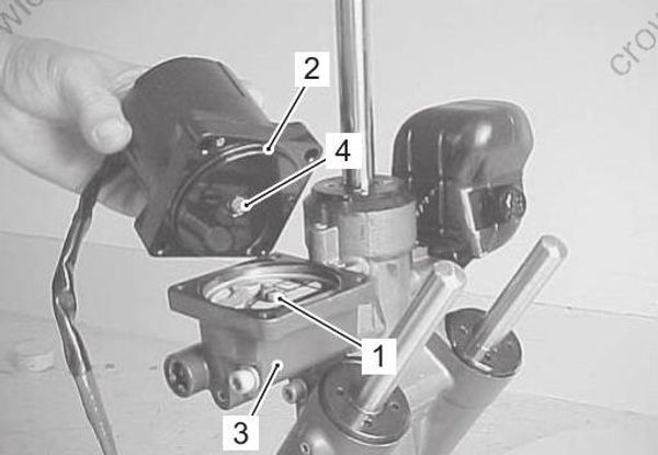
- Ensure that the drive joint (1) is aligned and firmly inserted into the gear pump assembly.
- Fit O-ring (2) to PTT motor.
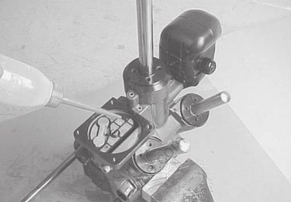
- Check the level of PTT fluid contained in the PTT pump assembly. If level is low, add recommended.
PTT fluid until level with mating surface of PTT motor.
- Ensure that the faces of the PTT motor and pump unit are free of dirt or debris.
When attaching the PTT motor to the PTT pump assembly (3), ensure that the tip of armature shaft (4) fits firmly into the drive joint (1).
- Tighten the four screws (a) to specified torque.
Tightening torque
PTT motor screws (a): 5 N·m (0.5 kgf-m, 3.6 lbf-ft)
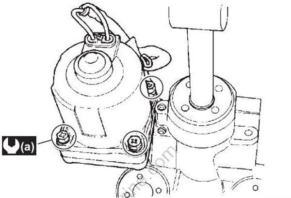
Pour recommended PTT fluid into reservoir until specified level.
Perform the air bleeding procedure.
Refer to “Power Trim and Tilt Unit Reassembly” (Page 2B-21).
Power Trim and Tilt Motor Disassembly and Assembly
Disassembly
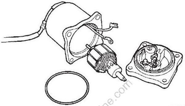
- For correct assembly, scribe an alignment mark on the field case and brush holder.
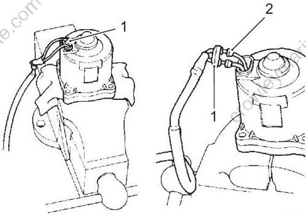
- Slide cable protector tube upward.
- Remove the screw securing the motor cable holder (1), then slide motor cable holder and grommets (2) out as shown in figure.
- Remove the two screws (3) securing the field case to the brush holder.
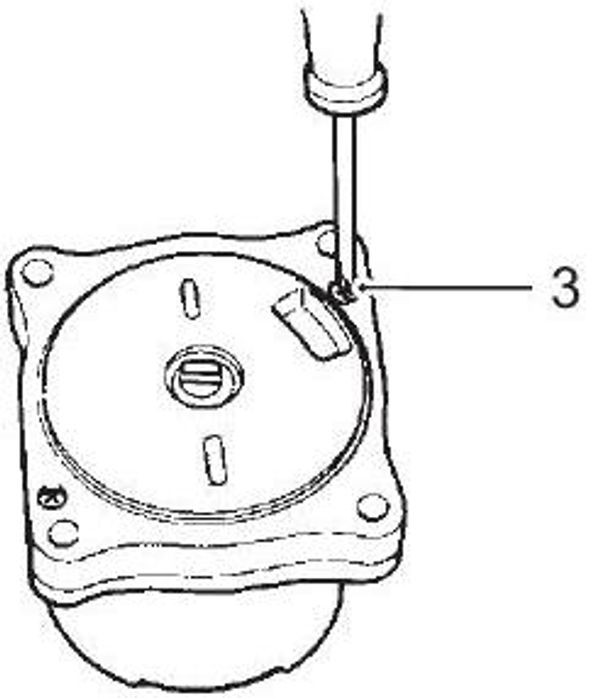
- Slide the field case upward and away from the brush holder.
When separating field case from brush holder, push the PTT motor cables into brush holder as the field case is removed.
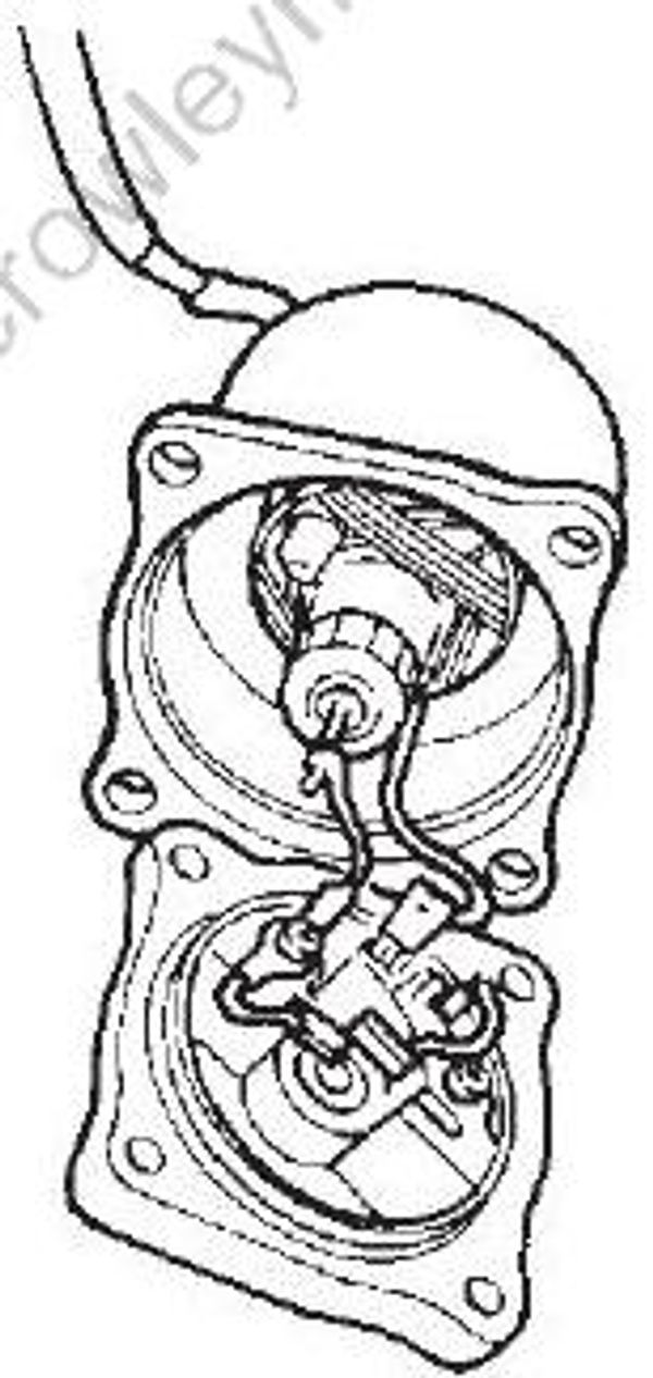
Disconnect PTT motor cables from brush holder.
Remove armature from field case. Note the position of the O-ring encircling the brush holder.
Assembly
Assembly is reverse of disassembly with special attention to following steps.
- Install O-ring (1).
- Install armature (2) to brush holder first. When installing the armature, use care to avoid breaking the brushes.
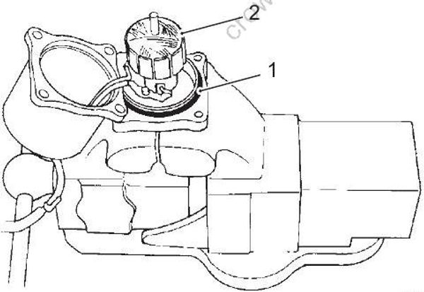
- Match up previously scribed alignment marks.
- When assembling field case to brush holder, pull out on the PTT motor cables as the field case is assembled into position.
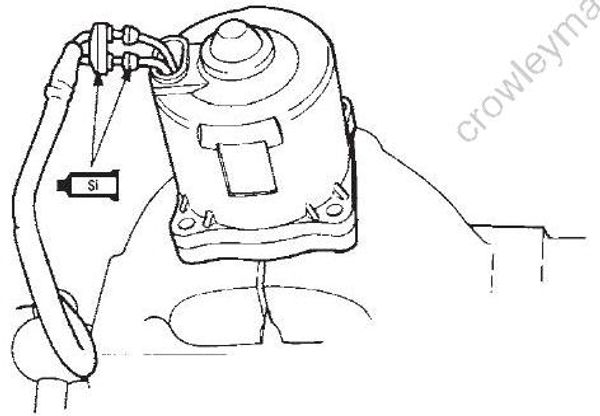
- Apply silicone seal to PTT motor cable holder and grommets and install cable holder screw.
: Sealant 93691–80030 (SUZUKI Silicone Seal (100 g))
PTT Motor Related Items Inspection
Armature and Commutator
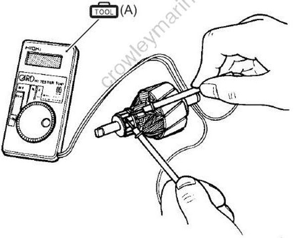
- Check for continuity between the commutator and the armature core/shaft. Replace armature if continuity is indicated.
Special tool
[TOOL] (A): 09900–25008 (Multi circuit tester set)
Tester knob indication
Continuity ( )
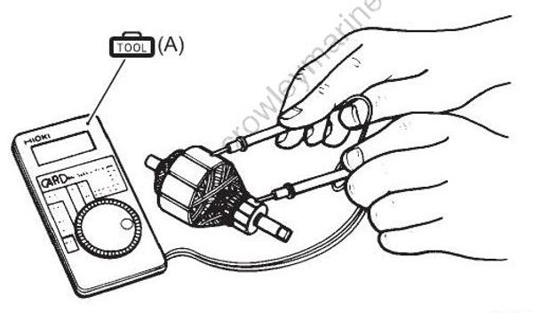
Check continuity between adjacent commutator segments.
Replace armature if no continuity is indicated.
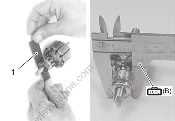
- Inspect the commutator surface.
If surface is gummy or dirty, clean with 400 grit emery paper (1).
- Measure commutator outside diameter.
If measurement exceeds service limit, replace armature.
Special tool
[TOOL] (B): 09900–20101 (Vernier calipers (150 mm))
Commutator outside diameter
Standard: 22.0 mm (0.87 in)
Service limit: 21.0 mm (0.83 in)
- Ensure that the mica (insulator) between commutator segments are undercut “a” to specified depth.
If undercut is less than service limit, cut to specified depth.
Failure to following proper precautions during use of the compressed air may cause severe personal injury.
Wear safety glasses when using compressed air.
Remove all particles of mica and metal using compressed air.
Commutator undercut
Standard: 1.6 – 1.9 mm (0.06 – 0.07 in.)
Service limit: 1.0 mm (0.04 in.)
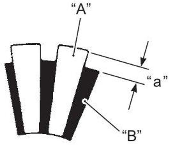
“A”: Segment
“B”: Mica
Brushes
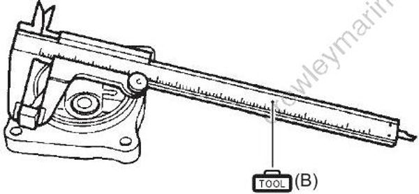
Check the length of each brush.
If brushes are worn down to the service limit, they must be replaced.
Special tool
[TOOL] (B): 09900–20101 (Vernier calipers (150 mm))
Brush length
Standard: 9.8 mm (0.39 in.)
Service limit: 5.5 mm (0.22 in.)
O-ring
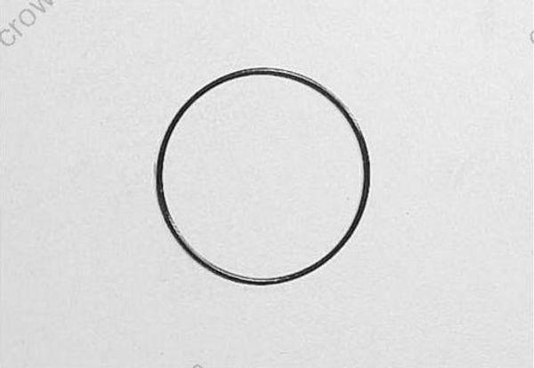
- Inspect the O-ring between the PTT motor and PTT pump assembly. Replace if cuts, nicks or tears are found.
PTT Motor Relay Inspection
Remove the PTT motor relay from the electric parts holder.
Refer to “Electric Parts Holder Removal and Installation” in Section 1D (Page 1D-3).
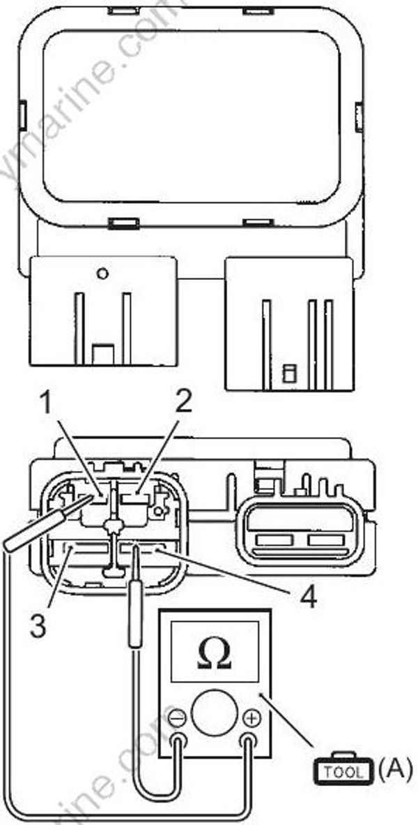
Check the resistance between each two terminals.
Special tool
[TOOL] (A): 09900–25008 (Multi circuit tester set)
Tester knob indication
Resistance (Ω)
PTT relay coil resistance
Between “terminal (1)” and “terminal (4)”: 16 – 24 Ω
Between “terminal (2)” and “terminal (4)”: 16 – 24 Ω
If the 12 V power supply wire is connected to wrong terminal or touched to each other, the power supply wire, tester may be damaged.
Be careful not to touch 12 V power supply wires to each other or with other terminals.
Check continuity between terminal (3) and (5) each time 12 V power supply is applied to terminal (1) and (4).
Connect the positive (+) lead to terminal (1), and negative (–) lead to terminal (4).
Check continuity between terminal (3) and (6) each time 12 V power supply is applied to terminal (2) and (4).
Connect the positive (+) lead to terminal (2), and negative (–) lead to terminal (4).
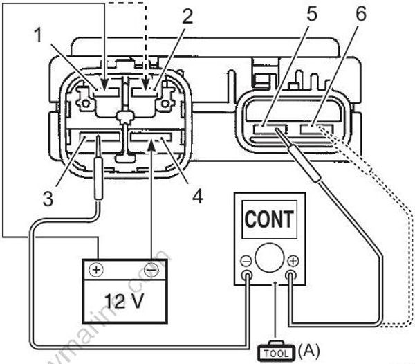
1.Terminal 1 (UP coil)
2.Terminal 2 (DN coil)
3.Terminal 3 (Power)
4.Terminal 4 (GND)
5.Terminal 5 (For UP)
6.Terminal 6 (For DN)
Special tool
[TOOL] (A): 09900–25008 (Multi circuit tester set)
Tester knob indication
Continuity ( )
PTT relay function
| Continuity | |
|---|---|
| 12 V power applied | Yes |
| 12 V power not applied | No |
If inspection in step 2 and/or step 3, 4 fails, replace PTT motor relay.
Install the PTT motor relay to the electric parts holder.
Refer to “Electric Parts Holder Removal and Installation” in Section 1D (Page 1D-3).
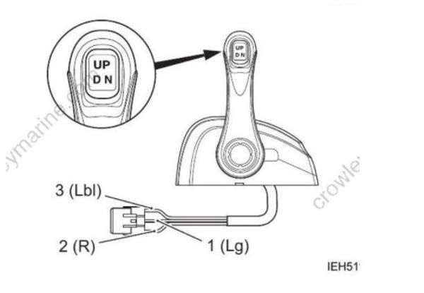
PTT Switch Inspection
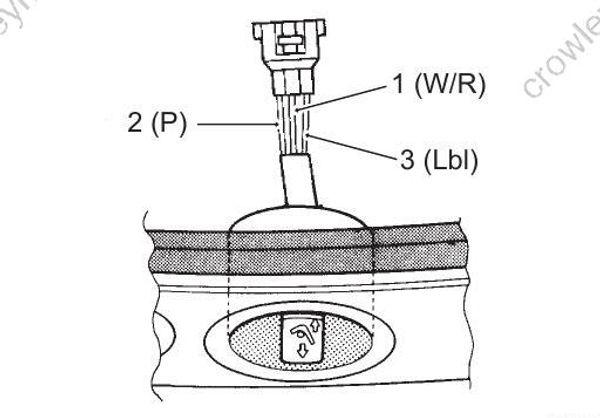
Test continuity between the switch lead wires at each of the three switch positions.
If out of specification, replace PTT switch.
Special tool
[TOOL] : 09900–25008 (Multi circuit tester set)
Tester knob indication
Continuity ( )
| Tester probe connection Red (+) | Tester probe connection Black (–) | Tester indicates | |
|---|---|---|---|
| DN side depressed | Terminal (2) | Terminal (1) | Continuity |
| UP side depressed | Terminal (3) | Terminal (1) | Continuity |
| Not depressed | Terminal (2) Terminal (3) |
Terminal (1) | Infinity |
Tilt Limit Switch Inspection
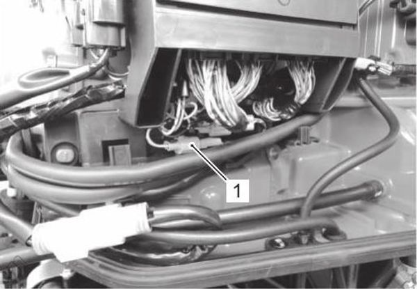
Disconnect the tilt limit switch lead wire connector (1).
Refer to “Electric Parts Holder Removal and Installation” in Section 1D (Page 1D-3).
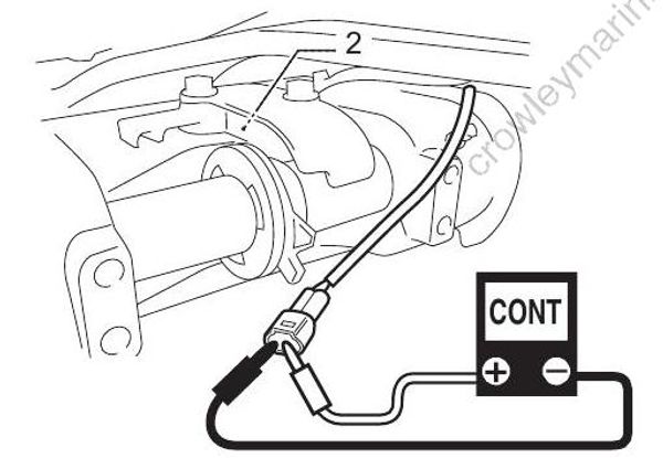
Test continuity between wires.
If out of specification, replace switch.
Refer to “Clamp / Swivel / Steering Brackets Disassembly” in Section 2A (Page 2A-19) and “Clamp / Swivel / Steering Brackets Assembly” in Section 2A (Page 2A-21).
Special tool
[TOOL] : 09900–25008 (Multi circuit tester set)
Tester knob indication
Continuity ( )
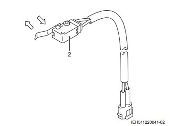
- Tilt limit switch
| Push the switch actuator plate.(Full tilt up position) | No continuity |
| Release the switch actuator plate.(Except for full tilt up position) | Continuity |
