

VVT (Variable Valve Timing) System Description
The VVT system is designed to continuously vary intake valve timing to best fit the engines current operating condition.
The intake cam timing sprocket assembly (VVT actuator) is located at the front end of the intake camshaft. The timing sprocket’ internal rotor is operated by engine oil pressure. Since the rotor and intake camshaft is bolted together, the rotor and camshaft move together. Varying the intake valve timing is accomplished by changing the intake camshaft phase angle relative to the intake cam timing sprocket using pressurized engine oil applied to the rotor through an ECM controlled oil control valve.
The oil control valve (OCV) directs engine oil pressure to the advance chamber or retard chamber inside the intake cam timing sprocket assembly (VVT actuator). The oil control valve operates on a duty cycle controlled by the ECM.
The ECM determines the optimum valve timing (advance angle) under various operating conditions based on engine speed, manifold pressure (throttle opening) and cylinder wall temperature. These input values are then used to control the position of the oil control valve (OCV). The ECM also detects the actual advance angle from the CMP sensor inputs to perform feedback control and accurately maintain the target advance angle.
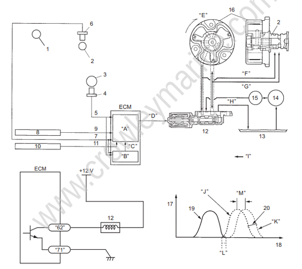
| 1. Ex. camshaft | 10. MAP sensor | 19. Ex. valve | “H”: Drain |
| 2. In. camshaft | 11. Manifold pressure signal | 20. In. valve | “I”: Engine oil pressure |
| 3. Crankshaft | 12. Oil control valve (OCV) | “A”: Target advance | “J”: Advance |
| 4. CKP sensor | 13. Oil pan | “B”: Actual valve timing | “K”: Retard |
| 5. Crank position | 14. Oil pump | “C”: Feed back | “L”: Valve overlap |
| 6. CMP sensor #2 | 15. Oil filter | “D”: Duty control | “M”: 40° movable angle |
| 7. Cam position signal | 16. VVT actuator | “E”: Rotation direction | |
| 8. Cylinder temp. sensor | 17. Valve lift | “F”: Retard pressure | |
| 9. Cylinder temp. signal | 18. Crank angle | “G”: Advance pressure |
OCV (Oil Control Valve)
The OCV is used to regulate oil flow and is installed on the lower camshaft housing.
Retard Operation
When the duty ratio of the ECM is small, the OCV spool valve is pushed away from the coil by spring force and engine oil pressure is applied to the retard chamber.
Engine oil remaining in the advance chamber is drained out through the spool valve.
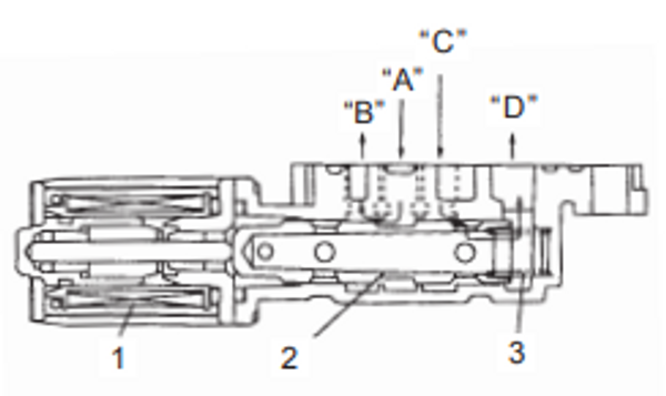
IEH511140010-03
| 1. Coil | “A”: Engine oil pressure | “D”: Drain |
| 2. Spool valve | “B”: To retard chamber | |
| 3. Spring | “C”: To advance chamber |
Advance Operation
When the duty ratio of the ECM is large, the spool valve is pulled towards the coil by magnetic force, compressing the spring and applying engine oil pressure to the advance chamber side.
Engine oil remaining in the retard chamber side is drained out through the spool valve.
Retaining Operation
When the duty ratio of the ECM is medium, the OCV coil’ magnetic and return spring forces are equal. This positions the spool valve between the advance and retard chamber, closing both oil passages.
Intake Cam Timing Sprocket Assembly
Inside the intake cam timing sprocket assembly (VVT actuator), there are separate advance and retard chambers formed by a partition of the rotor.
The rotor moves inside the housing as engine oil pressure is applied to the advance or retard chamber.
The intake cam timing sprocket is part of the sprocket housing assembly. Since the rotor and intake camshaft are bolted together, when the rotor moves inside the housing, a change of phase angle takes place in the relative position between the intake camshaft and intake cam timing sprocket. The rotor has a spring pressured lock pin which engages with the housing when spring force is greater than oil pressure, locking the rotor in the most retarded position. This prevents a change of phase angle between the intake camshaft and intake cam timing sprocket when the engine oil pressure is low at engine start.
When the engine is started and the engine oil pressure is applied to the advance chamber, the lock pin is forced up, compressing the return spring, releasing the rotor and allowing the VVT actuator to function.
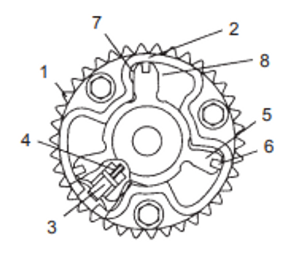
IEH511140011-03
| 1. Intake cam timing sprocket | 5. Rotor |
| 2. Housing | 6. Seal |
| 3. Lock pin | 7. Advance chamber |
| 4. Spring | 8. Retard chamber |
