

Component Location
Engine Control System Components / Engine Electrical Device Location
Refer to “Wiring Harness Routing Diagram” in Section 4A (Page 4A—4).
Diagnostic Information and Procedures
ECM Power and Ground Circuit Check
Wiring Diagram
Normal key start model

| 1. Battery | 4. Main switch | 7. BCM |
|---|---|---|
| 2. 30 A fuse | 5. ECM main relay | “A": To 30 A main relay fuse |
| 3. Sub battery cable | 6. ECM | “B": To neutral switch |
Keyless start model
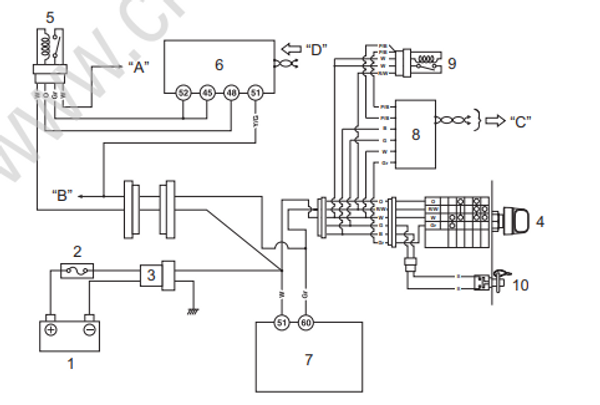
| 1. Battery | 5. ECM main relay | 9. ECM power relay | “C": To ECM |
|---|---|---|---|
| 2. 30 A fuse | 6. ECM | 10. Emergency stop switch | “D": From keyless control unit |
| 3. Sub battery cable | 7. BCM | "A" To 30 A main relay fuse | |
| 4. Main switch | 8. Keyless control unit | “B": To neutral switch |
