Power Trim and Tilt Description
- The power trim and tilt system components are an electric motor, a pump unit, a fluid reservoir and trim/tilt cylinders.
The outboard can be trimmed “UP" or “DOWN" while under way, and can be tilted for beaching, operating in shallow water or trailering.
Trim and tilt “UP” or “DOWN” is obtained by supplying power to a permanent magnet type motor. This motor will rotate clockwise for “UP” or counterclockwise for “DOWN", according to power delivered via the PTT relay, which is mounted on the electric part holder.
Power Trim and Tilt Hydraulic Diagram
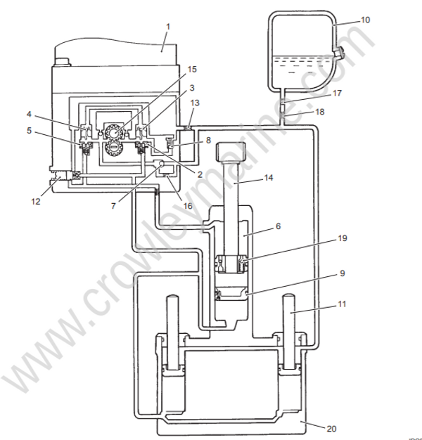
| 1. PTT motor |
| 2. Up check valve |
| 3. Up shuttle valve |
| 4. Down shuttle valve |
| 5. Down check valve |
| 6. Tilt cylinder Upper chamber |
| 7. Down relief check valve |
| 8. Up relief valve |
| 9. Free piston |
| 10. Oil reservoir |
| 11. Trim rod |
| 12. Manual release valve |
| 13. Pump room orifice |
| 14. Tilt rod |
| 15. Gear pump |
| 16. Down relief orifice |
| 17. Filter |
| 18. Tank room orifice |
| 19. Impact relief valve |
| 20. Cylinder body |
Principles of Power Trim and Tilt Operation Description
By motor operation, the geared pump will be driven, and by turning the motor to the right or to the left, oil flow will change its direction. This causes “UP” and “DOWN” movements of the piston rod of the tilt cylinder and the trim rod of the trim cylinder.
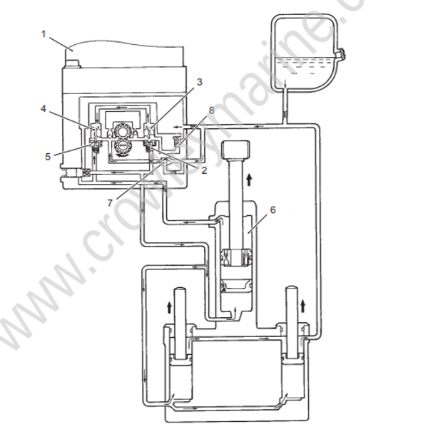
Trim Tilt Up Circuit
When the PTT switch is operated “UP" position, the electric motor and gear pump (1) will operation on clockwise direction.
Pressurized oil will open “Up” check valve (2) and the oil will flow through ”Up” shuttle valve (3) to the “Down" shuttle valve (4). Following operation of valve (4), “Down" check valve (5) will open mechanically.
Pressurized oil flows through the “Up” check valve (2) to the bottom of the trim and tilt cylinders, thereby pushing the trim and tilt pistons upward.
Residual oil in the upper area of the tilt cylinder (6) is returned to the pump through “Down" check valve (5).
Any oil in the area above both trim cylinder pistons will be returned to the reservoir.
Oil will then flow from the reservoir to the pump to stabilize the balance of the oil volumes.
When the engine is fully tilted up, oil pressure will correspondingly increase in the lower chamber of the tilt and trim cylinders. But, to protect the PTT unit from excessively high pump pressure, the “Up" relief valve (8) begins to open.
Trim / Tilt Down Circuit
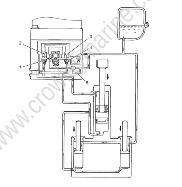
When the PTT switch is operated in the “DOWN” position, the electric motor will rotate in a counterclockwise direction and turn the gear pump.
The oil pressure will open the ”Down" check valve (1) and oil will be forced through the “Down" shuttle valve (2).
When the oil reaches “Up” shuttle valve (3), the “Up check valve (4) will begin to open mechanically.
The pressurized oil flows through “Down" check valve (1) and then enters the upper area of the tilt cylinder.
This thereby forces the tilt rod piston downward.
When the swivel bracket contacts the trim rams, this pressure forces the trim pistons downward and oil from the
reservoir is then able to enter the area above both trim rod pistons.Oil from the lower area of the trim and tilt cylinders now returns to the pump through “Up” check valve (4).
Throughout the tilt action operation range, there is a difference in oil volume between the upper and lower chambers of the tilt cylinder, and any surplus oil is therefore directed to the reservoir by means of the “Down" relief orifice (5).
Throughout trim operation range, oil will be discharged from the bottom of all three cylinders and the pump will only supply oil to the tilt cylinder. Excess oil is then vented to the reservoir through the “Down" relief orifice (5).
To prevent damage from excessive oil pressure when all three rods are fully retraced, this pressure is relieved through the “Down" relief orifice (5).
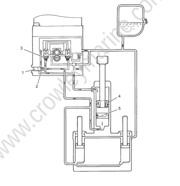
Shock Absorber Circuit
This incorporated safety feature is for protection of the gearcase and prevention of internal PTT pressure build-up in the event of an impact.
The pressure from a sudden impact will make impact relief valve (1) open, allowing oil from the upper area of the tilt cylinder to flow into the area between the tilt rod piston and the free piston. The tilt rod will then extend.
When the moment of impact has passed, the PTT DOWN switch must be activated to return the engine to within the normal trim range. When the switch is pressed, the oil between the piston and free piston will be directed to the cylinder upper chamber via the return valve below the tilt piston.
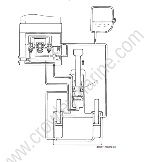
Manual Release Circuit (Down Mode)
By opening the manual release valve (1), the engine can be lowered manually to a running position. Oil underneath the trim and tilt pistons will be directed through this valve into the area above the tilt rod piston.
The volume of oil flowing from under the trim rod pistons will be larger than the area above the tilt rod piston can accommodate. Excess oil therefore returns through the manual release valve (1) to the reservoir.
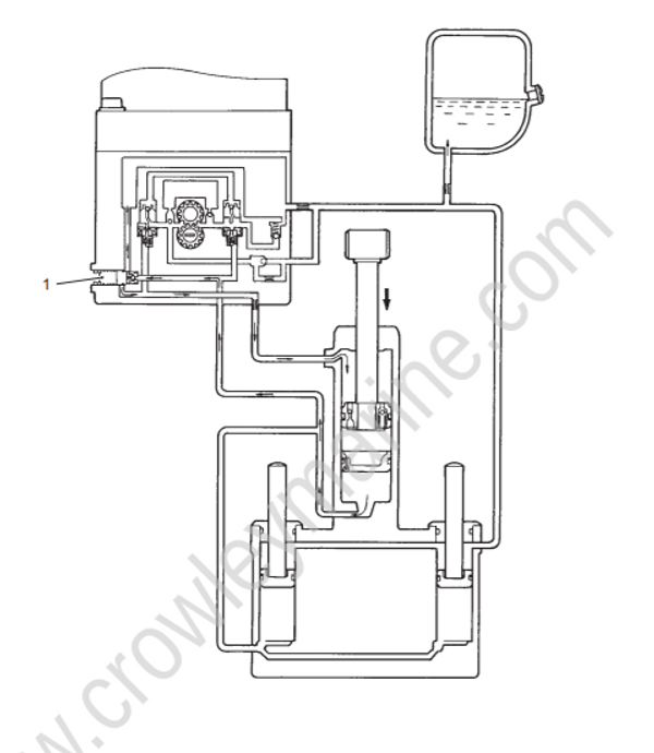
Manual Release Circuit (Up Mode)
With the manual release valve (1) open, the engine can also be raised manually to the fully tilted position.
Oil from the upper chamber of the tilt cylinder will flow through valve (1) into the lower chamber of the cylinder.
The upward movement of the piston rod will increase the cylinder area beneath it, thereby allowing oil from the reservoir to flow into this area.
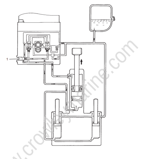
Tilt System Pressure Relief
If engine speed exceeds approx. 1500 r/min when operating in shallow water drive mode, oil pressure will increase underneath the tilt piston. The relief valve (2) (incorporated in the manual release valve (1)) will then open.
The oil below the tilt piston will then flow to the reservoir through the relief valve (2).
As the power of the engine continues to exert downward force on the tilt piston, this will open “Down" check valve (3), thereby allowing oil from the reservoir to flow into the chamber above the tilt piston.
In this way, high internal pressure is relieved and the engine will slowly tilt downward until it reaches the highest
position in the Trim range.
Thermal Expansion Relief
High ambient temperature will, through thermal expansion, induce a build—up of oil pressure inside the PTT unit.
Expansion of the oil and the resulting high pressure will open the relief valve (2), thereby providing unit protection by directing oil back to the reservoir.
Expanded oil in the tilt cylinder upper chamber will return to reservoir passing through impact relief valve (4) —> free piston check valve (5) —> thermal relief valve (2).