

Precautions
Precautions for Maintenance
The “Periodic Maintenance Schedule Chart” lists the recommended intervals for all the required periodic service work necessary to keep the motor operating at peak performance and economy.
Maintenance intervals should be judged by number of hours or months, whichever comes first.
More frequent servicing should be performed on outboard motors that are used under severe conditions.
General Description
Recommended Oil and Lubricants
Refer to “Fuel and Oil Recommendations” in Section 0A (Page 0A-4).
Scheduled Maintenance
Periodic Maintenance Schedule Chart
I = Inspect and clean, adjust, lubricate or replace, if necessary
T = Tighten
R = Replace
| Item to be serviced | Interval | Interval | Interval | Interval |
|---|---|---|---|---|
| Initial 20 hrs. or 1 month | Every 100 hrs. or 12 months | Every 200 hrs. or 12 months | Every 300 hrs. or 36 months | |
| Spark plug | — | I | — | — |
| Breather & Fuel line | I | I | — | — |
| Engine oil | R | R | — | — |
| Gear oil | R | R | — | — |
| Lubrication | I | I | — | — |
| Anodes (External) | I | I | — | — |
| Anodes (Internal powerhead) | — | I | — | — |
| Bonding wires | I | I | — | — |
| Battery | I | I | — | — |
| Engine oil filter | R | — | R | — |
| High pressure fuel filter | Replace every 1 000 hours | Replace every 1 000 hours | Replace every 1 000 hours | Replace every 1 000 hours |
| Low pressure fuel filter | I | I | — | — |
| Low pressure fuel filter | Replace every 400 hours or 2 years. | Replace every 400 hours or 2 years. | Replace every 400 hours or 2 years. | Replace every 400 hours or 2 years. |
| Ignition timing | — | — | I | — |
| Idle speed | I | — | I | — |
| Balancer chain | Replace every 1 600 hours | Replace every 1 600 hours | Replace every 1 600 hours | Replace every 1 600 hours |
| Tappet clearance | — | — | — | I |
| Water pump | — | — | I | — |
| Water pump impeller | — | — | I | R |
| Propeller nut & pin | I | I | — | — |
| Bolt & Nuts | T | T | — | — |
| Thermostat | — | I | — | — |
Lubrication Point
Proper lubrication is important for the safe, smooth operation and long life of each working part of the outboard motor. Apply Suzuki Water Resistant Grease to the following point.
Lubricate
Initially after 20 hours (1 month) and every 100 hours (12 months)
Grease 99000–25350 (SUZUKI Water Resistant Grease EP2 (250 g))
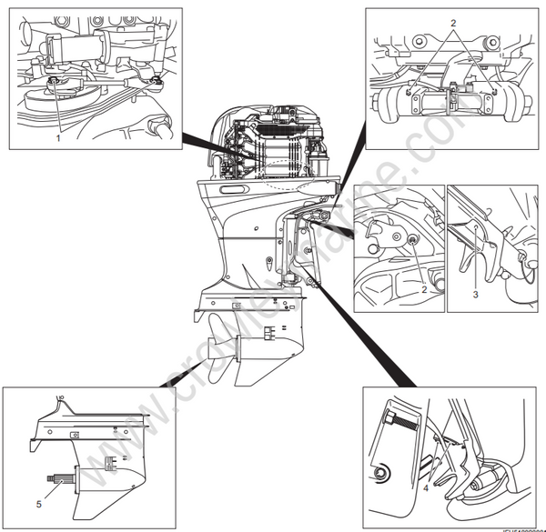
| 1. Shift linkage |
| 2. Grease nipple, swivel bracke |
| 3. Grease nipple, steering bracket |
| 4. Trim ram pad |
| 5. Propeller shaft |
Engine Oil Level Check
Inspect oil level
Before every use
Place outboard motor upright on a level surface.
Remove motor cover.
Remove the oil level dipstick (1) and wipe it clean.
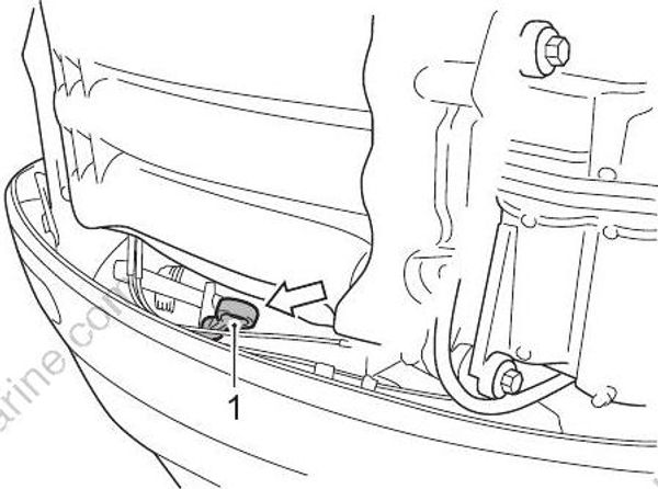
Reinsert dipstick fully into dipstick tube, then remove it to check oil level.
Oil level should be between full level Max. mark (hole) and low level Min. mark (hole).
If level is low, add recommended oil to full level Max. mark.
Recommended engine oil
4 stroke motor oil
NMMA certified FC-W oil. or API classification: SG, SH, SJ, SL, SM.
Viscosity rating: SAE 10W-40 or 10W-30, NMMA FC-W 10W-40 or 10W-30
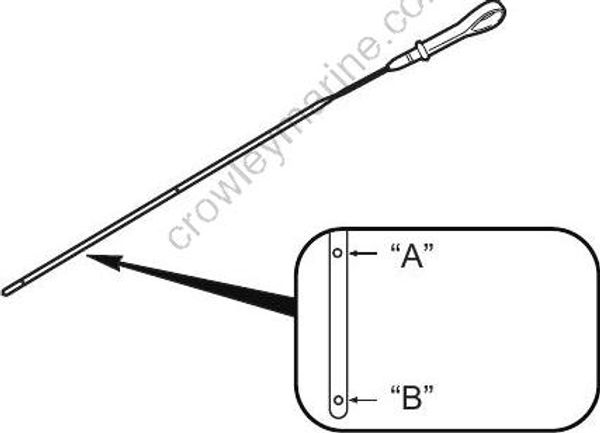
| “A”: Max. mark (hole) |
| “B”: Min. mark (hole) |
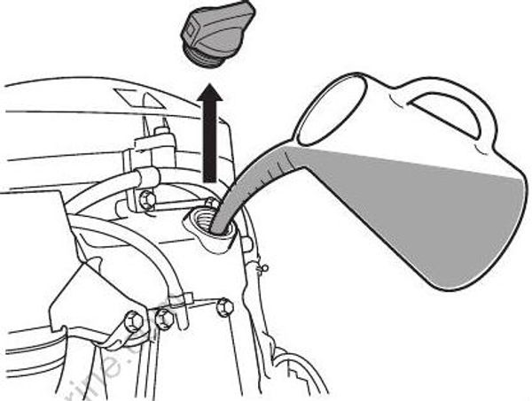
Engine Oil Change and Engine Oil Filter Replacemen
Change engine oil
Initially after 20 hours (1 month) and every 100 hours (12 months)
Replace engine oil filter/Initially after 20 hours (1 month) and every 200 hours (12 months)
• Engine oil should be changed while engine is warm.
• When replacing engine oil filter, change engine oil at the same time.
Engine Oil Change
Place outboard motor upright on a level surface.
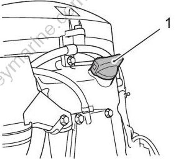
Remove oil filler cap (1).
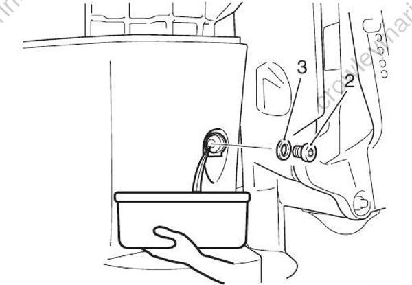
Place a container under engine oil drain plug.
Remove engine oil drain plug (2) and gasket (3) to drain engine oil.
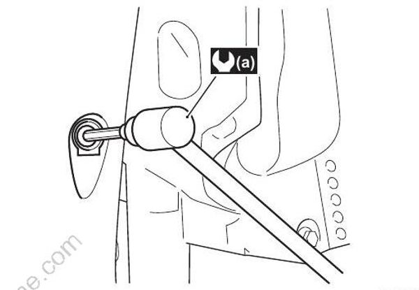
- Install new gasket and oil drain plug.
Tighten engine oil drain plug to specified torque.
A previously-used gasket may leak, resulting in engine damage.
To avoid water entry into oil pan or oil leakage into the environment do not reuse gasket once removed.
Always use a new one.
Tightening torque
Engine oil drain plug (a): 13 N·m (1.3 kgf-m, 9.5 lbf-ft)
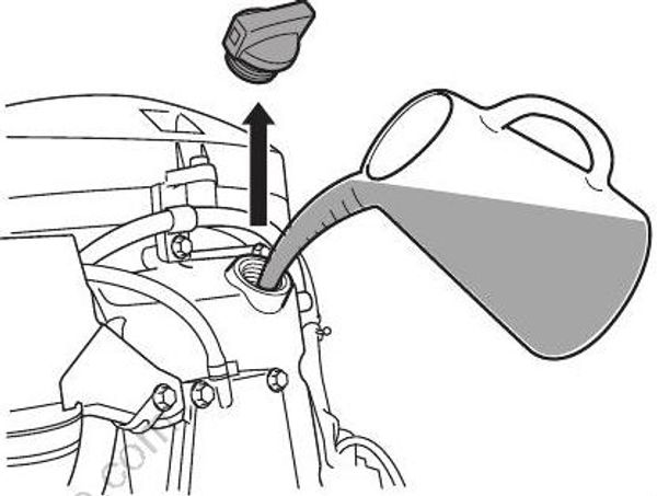
- Pour recommended engine oil into oil filler opening, then install oil filler cap.
Recommended engine oil
4 stroke motor oil
NMMA certified FC-W oil. or API classification: SG, SH, SJ, SL, SM.
Viscosity rating: SAE 10W-40 or 10W-30, NMMA FC-W 10W-40 or 10W-30
Engine oil amounts
Oil change only: 8.0 L (8.5/7.0 US/lmp.qt)
Oil filter change: 8.5 L (9.0/7.5 US/lmp.qt)
- Reset oil change reminder system’s operation time to zero (cancellation).
Refer to “Oil Change Reminder System Description” in Section 1A (Page 1A-28).
- Start engine and allow it to run for several minutes at idle speed.
Check oil drain plug for oil leakage.
Turn off engine and wait for approx. two minutes, then recheck engine oil level.
Engine Oil Filter Replacement
Drain engine oil in the same manner of engine oil change procedure.
Remove STBD lower side cover.
Refer to “Lower Side Cover Removal and Installation” in Section 2A (Page 2A-3).
Place a shop cloth under the oil filter before removal to absorb any oil released.
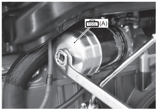
Using the oil filter wrench to loosen the oil filter, then remove the filter and O-ring.
Special tool
(A): 09915–47341 (Oil filter wrench)
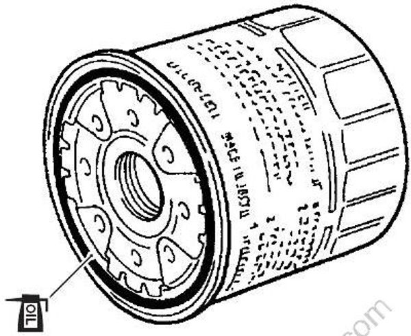
Before fitting a new oil filter, be sure to oil the O-ring.
Screw the new filter on by hand until filter O-ring contacts the mounting surface.
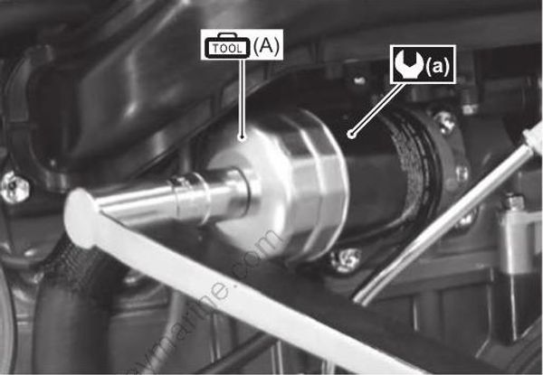
Tighten the filter 3/4 turn from the point of contact with mounting surface using the oil filter wrench.
Tightening torque
Engine oil filter (a): 14 N·m (1.4 kgf-m, 10.0 lbf-ft)
- Install STBD lower side cover.
Refer to “Lower Side Cover Removal and Installation” in Section 2A (Page 2A-3).
- Pour the recommended engine oil into the oil filler opening, then install oil filler cap. Check the oil level in the same manner of engine oil change procedure.
Recommended engine oil
4 stroke motor oil
NMMA certified FC-W oil. or API classification: SG, SH, SJ, SL, SM.
Viscosity rating: SAE 10W-40 or 10W-30, NMMA FC-W 10W-40 or 10W-30
Engine oil amounts
Oil change only: 8.0 L (8.5/7.0 US/Imp.qt)
Oil filter change: 8.5 L (9.0/7.5 US/Imp.qt)
- Reset oil change reminder system’s operation time to zero (cancellation).
Refer to “Oil Change Reminder System Description” in Section 1A (Page 1A-28).
- Start engine and allow it to run for several minutes at idle speed.
Check oil filter for oil leakage.
Turn off engine and wait for approx. two minutes, then recheck engine oil level.
Gear Oil Change
Change gear oil
Initially after 20 hours (1 month) and every 100 hours (12 months)
Place outboard motor upright on a level surface.
Place a container under the lower unit.
Remove lower gear oil drain plug (1) first, then remove air vent plug (2) and drain gear oil.
The air vent plug, oil level plug and the oil drain plug are now different.
The magnet is installed in the drain plug. Clean the magnet if there is a metal powder on it.
Do not make a mistake in their positions when install them.
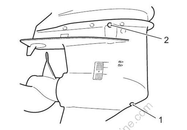
- Fill with recommended gear oil through oil drain hole until oil just starts to flow out from air vent hole.
Recommended gear oil
- Suzuki Outboard Motor Gear Oil or API classification GL5, Viscosity rating SAE # 90 Hypoid gear oil.
Gear oil amount
1 100 ml (37.2/38.7 US/Imp. oz)
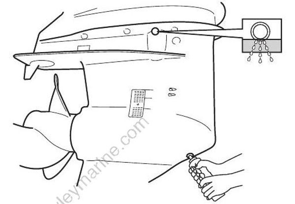
Install air vent plug before removing oil filler tube from drain hole.
Install oil drain plug.
An used gasket may leak and allow water to enter the gearcase causing severe damage.
Do not reuse gaskets once removed. Always use new gaskets.
To avoid a possible low gear oil level, recheck gear oil level 10 minutes after doing procedure in step 6. If oil level is low, add additional gear oil until level is correct.
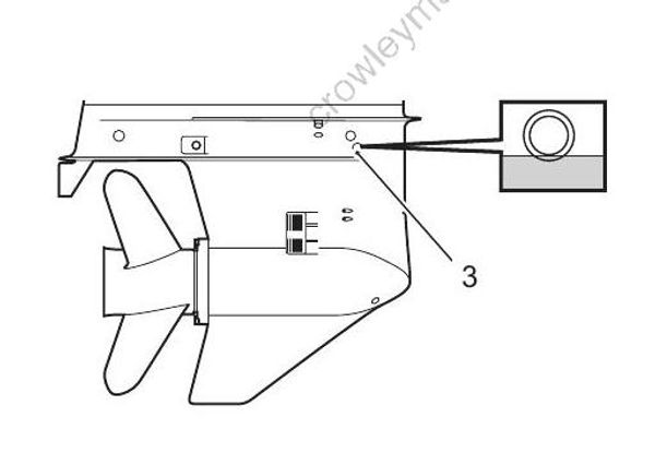
- To check the gear oil level:
a) Remove the oil level plug (3).
b) If oil can be seen at oil level plug level, the unit is full.
c) If oil level is low, re-fill with gear oil through oil level hole.
d) Install oil level plug.
Spark Plug Removal and Installation
Inspect spark plug / Every 100 hours (12 months)
Standard spark plug / NGK LKR6E
Non-resistor types of spark plugs will interfere with the function of the electronic ignition, causing misfiring, or causing problems with other electronic boat equipment and accessories.
Only resistor (R) type spark plugs must be used with this engine.
Removal
The hot engine can burn you.
Wait until the engine is cool enough to touch.
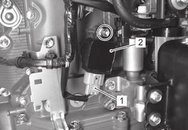
- Disconnect the ignition coil connectors (1).
Remove the bolts and ignition coils (2).
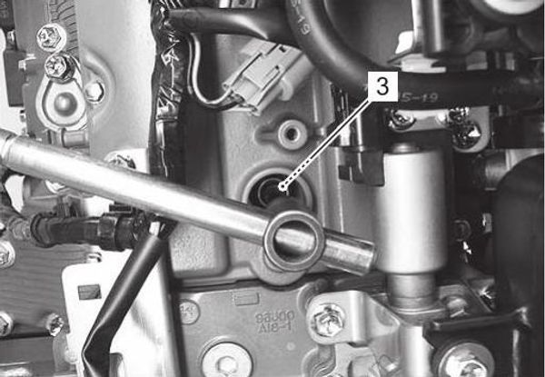
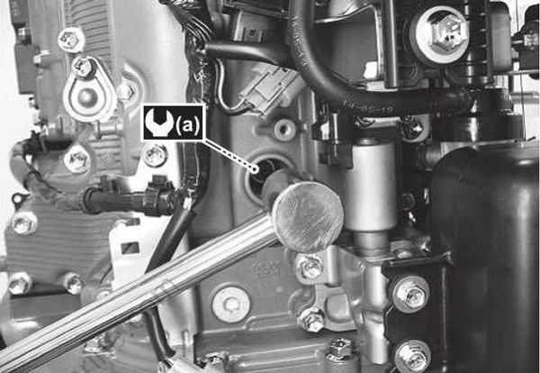
- Remove the spark plugs (3) with spark plug wrench.
Installation
Installation is reverse order of removal.
Pay attention to the following:
- Tighten the spark plug to specified torque.
Tightening torque
Spark plug (a): 17 N·m (1.7 kgf-m, 12.3 lbf-ft)
Spark Plug Inspection and Cleaning
Non-resistor types of spark plugs will interfere with the function of the electronic ignition, causing misfiring, or causing problems with other electronic boat equipment and accessories.
Only resistor (R) type spark plugs must be used with this engine.
Inspect spark plug / Every 100 hours (12 months)
Standard spark plug / NGK LKR6E
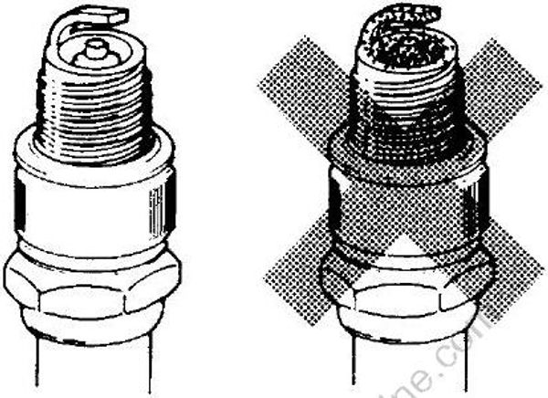
Carbon Deposits
Inspect for carbon deposits on spark plug base.
If carbon is present, remove it with a spark plug cleaning machine or by carefully using a pointed tool.
Spark Plug Gap
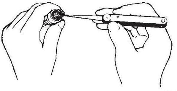
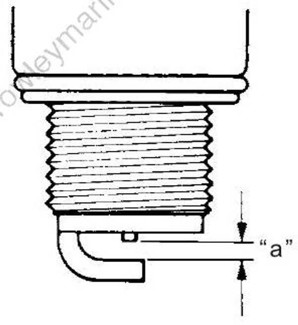
Measure spark plug gap with a thickness gauge. Adjust to within specified range if gap is out of specification.
Special tool : 09900–20803 (Thickness gauge)
Spark plug gap “a” (Standard)
0.8 – 0.9 mm (0.031 – 0.035 in.)
Condition of Electrodes
Inspect electrode for a worn or burnt condition.
If it is extremely worn or burnt, replace spark plug.
Also, be sure to replace spark plug if it has a broken insulator, damaged thread, etc.
Use of improper spark plugs can cause severe engine damage. If the reach is too short, carbon will be deposited on the threaded portion of the plug hole resulting in possible engine damage.
Confirm the thread size and reach when replacing the plug.
Tappet Clearance Inspection and Adjustment
Inspect tappet clearance / Every 300 hours (36 months)
Inspection
The tappet clearance specification is different for intake and exhaust valves.
Too small a tappet clearance may reduce engine power, too large a tappet clearance increases valve noise and hastens valve and seat wear.
When the tappets are set to the specified clearance, the engine will run without excessive noise from the valve mechanism and will deliver full power. In this engine, the tappet clearance is increased or decreased by replacing the shim disc, made of a special wear resistant material, fitted to the top of the tappet. Using the proper tools provides for easy removal and installation of the shim disc.
Tappet clearance adjustment should be checked and adjusted:
During scheduled periodic inspection.
When valve mechanism is serviced.
When camshafts are disturbed by removing them for inspection.
- Remove the lower side covers.
Refer to “Lower Side Cover Removal and Installation” in Section 2A (Page 2A-3).
- Remove the ring gear cover and air intake silencer case (1).
Refer to “Air Intake Silencer Case Removal and Installation” in Section 1D (Page 1D-2).
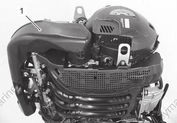
- Remove all spark plugs.
Refer to “Spark Plug Removal and Installation” (Page 0B-7).
- Remove the cylinder head cover (2).
Refer to “Cylinder Head Cover Removal and Installation” in Section 1D (Page 1D-15).
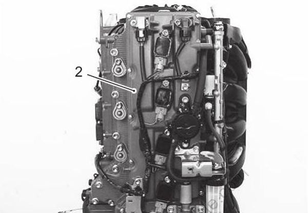
- Rotate crankshaft counterclockwise to bring cam nose vertical to shim surface.
This is a left hand (LH) rotation powerhead.
Turning of the engine in clockwise can cause water pump impeller damage.
Rotate the crankshaft in the normal running direction only (counterclockwise) to prevent water pump impeller damage.
- Measure tappet clearances by inserting thickness gauge between cam and shim surface.
• Rotate crankshaft and measure clearance for each tappet respectively by bringing cam nose vertical to shim surface.
• All tappet clearances can be measured during two crankshaft rotations.
Special tool
(A): 09900–20803 (Thickness gauge)
Tappet clearance (Cold engine condition)
IN.: 0.23 – 0.27 mm (0.009 – 0.011 in.)
EX.: 0.30 – 0.34 mm (0.012 – 0.013 in.)
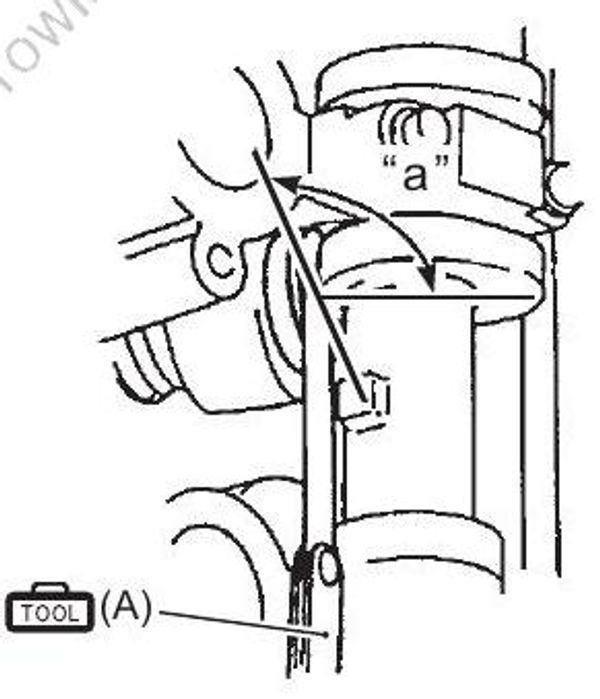
“a”: 90°
- If out of specification, adjust tappet clearance by changing shim.
Adjustment
Tappet clearances are adjusted by replacing tappet shim.
- With cam nose vertical to valve, turn tappet cut-away towards center of cylinder head as shown in figure.
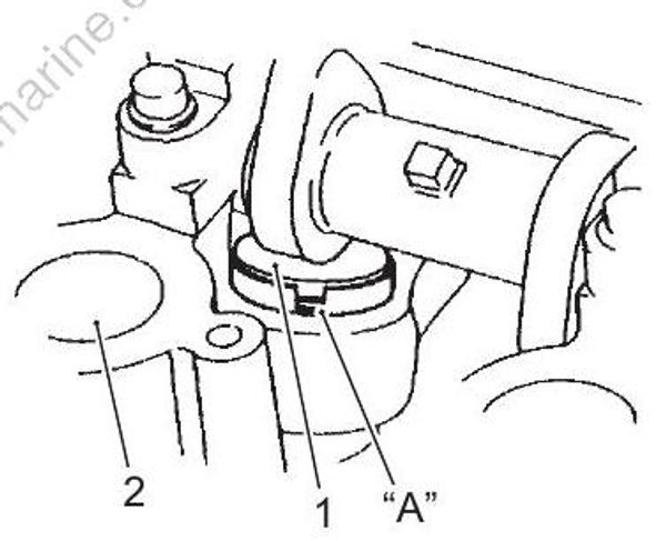
| 1. Shim |
| 2. Spark plug hole |
| “A”: Cut section of the tappet |
Rotate crankshaft to open (lift up) valve and then remove camshaft housing bolts where shim is to be replaced.
Install special tool with camshaft housing bolts as shown in figure.
Special tool
(A): 09916–69310 (Tappet holder)
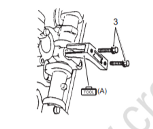
| 3. Camshaft housing bolt |
Failure to take proper precautions when installing or removing the tappet shim can result in severe personal injury.
When installing or removing the tappet shim:
• Never put in the hand between camshaft and tappet.
• Use a magnet to remove and install shim.
- Rotate top of cam 90 degree clockwise and remove shim from cut-away at tappet.
(Two tappets can be adjusted at the same time)
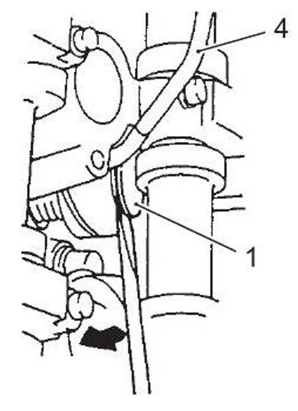
| 1. Shim |
| 4. Magnet |
When installing shim, identification mark on the shim should face down (towards tappet).
- After removing shim, measure thickness of original shim and determine correct thickness of shim for proper tappet clearance as calculated by following formula.
Special tool
(B): 09900–20205 (Micrometer (0 – 25 mm))
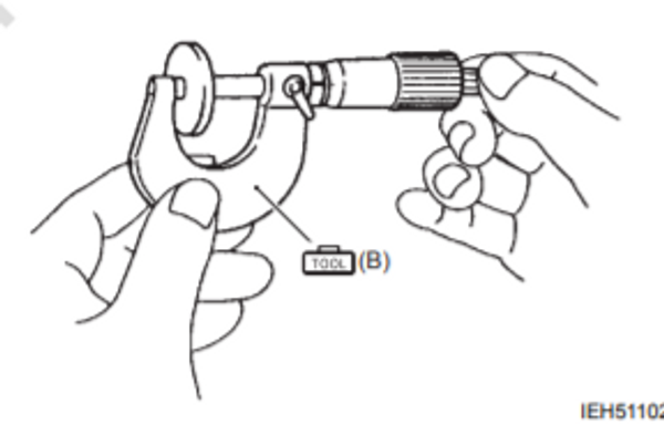
Tappet clearance specifications
IN. side: A = B + (C – 0.25 mm)
EX. side: A = B + (C – 0.32 mm)
A: Correct thickness of shim for proper tappet clearance (mm)
B: Thickness of original shim (mm)
C: Original tappet clearance (mm)
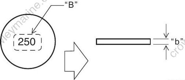
| “B”: I.D No. |
| “b”: 2.50 mm |
Shim size chart
| I.D. No. | Thickness (mm) | I.D. No. | Thickness (mm) |
|---|---|---|---|
| 218 | 2.18 | 260 | 2.60 |
| 220 | 2.20 | 263 | 2.63 |
| 223 | 2.23 | 265 | 2.65 |
| 225 | 2.25 | 268 | 2.68 |
| 228 | 2.28 | 270 | 2.70 |
| 230 | 2.30 | 273 | 2.73 |
| 233 | 2.33 | 275 | 2.75 |
| 235 | 2.35 | 278 | 2.78 |
| 238 | 2.38 | 280 | 2.80 |
| 240 | 2.40 | 283 | 2.83 |
| 243 | 2.43 | 285 | 2.85 |
| 245 | 2.45 | 288 | 2.88 |
| 248 | 2.48 | 290 | 2.90 |
| 250 | 2.50 | 293 | 2.93 |
| 253 | 2.53 | 295 | 2.95 |
| 255 | 2.55 | 298 | 2.98 |
| 258 | 2.58 | 300 | 3.00 |
Install shim with the identification number facing down (towards tappet).
Rotate crankshaft clockwise to open (lift up) valve.
This step only; Rotate the crankshaft clockwise, otherwise the valves may contact with the piston head.
- Remove special tool and tighten camshaft housing bolts (a) to specified torque.
Tightening torque
Camshaft housing bolt (a): 12 N·m (1.2 kgf-m, 8.5 lbf-ft)
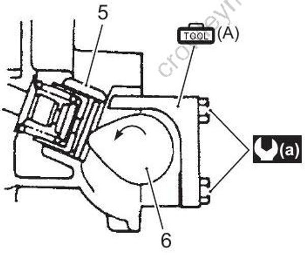
| 5. Tappet |
| 6. Camshaft |
- Recheck tappet clearance.
After completing tappet clearance adjustment and securing camshaft housing bolts, inspect tappet clearance again.
- After checking and adjusting all valves, reinstall parts removed earlier.
Installation is reverse order of removal.
a) Cylinder Head Cover.
- Install the cylinder head cover.
Refer to “Cylinder Head Cover Removal and Installation” in Section 1D (Page 1D-15).
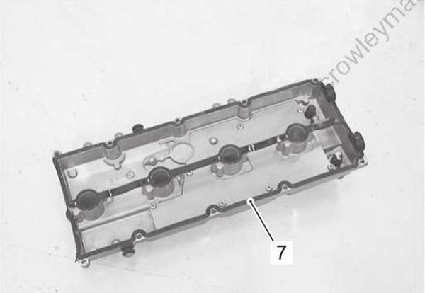
Examine cylinder head cover gasket (7) for damage. Always replace gasket if sealing performance is suspect.
b) OCV
- Install OCV.
Refer to “OCV (Oil Control Valve) Removal and Installation” in Section 1D (Page 1D-18).
An used gasket may leak, resulting in engine damage.
Do not reuse gasket once removed. Always use a new gasket.
c) Final assembly check
All parts removed have been returned to their original positions.
Check hose and wire routing.
Refer to “Wiring Harness Routing Diagram” in Section 4A (Page 4A-4).
- Check oil leakage.
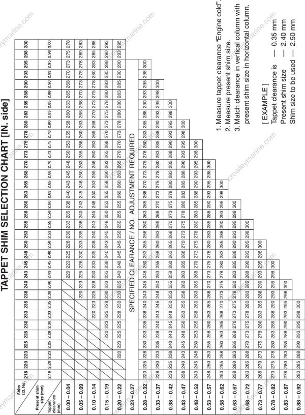
Tappet shim selection chart (IN. side)
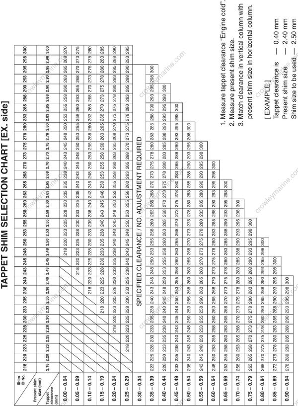
Tappet shim selection chart (EX. side)
Idle Speed Inspection
Inspect idle speed / Initially after 20 hours (1 month) and every 200 hours (12 months)
Before checking idle speed, make sure of the following.
• Engine must be warmed up.
• Check idle speed after engine speed has stabilized.
• Check throttle mechanism and throttle valve for smooth operation.
• Lead wires and hoses of electronic fuel injection and engine control systems are connected securely.
• Ignition timing is within specification.
• Tappet clearance is checked according to maintenance schedule.
• No abnormal air drawn in from air intake system.
After all items are confirmed, check idle speed.
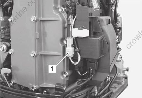
| 1. SDS service connector |
Check idle speed as follows. To perform idle speed inspection, use personal computer and SDS tool.
- Connect SDS tool to engine.
Refer to SDS operation manual for the step 1 procedure.
Start engine and allow to warm up.
Check engine speed by using “Service data/Engine data” mode on SDS.
If idle speed is out of specification, inspect throttle control system referring to “Electronic Throttle System Inspection”.
Idle speed in neutral gear
600 – 700 r/min
- Shift into forward, check in-gear idle speed. If not, inspect throttle control system.
Idle speed in-gear
600 – 700 r/min
• Trolling speed (in-gear idle speed) is same as idle speed.
• Idling/trolling speed of 600 – 700 r/min is controlled by electronic throttle system.
• This throttle system is not equipped with IAC valve for idle speed control.
• Idle speed control is done by the throttle actuator which controls the throttle valve opening. Refer to “Electronic Throttle System Description” in Section 1G (Page 1G-9).
• If engine idle speed is out of specification, electronic throttle system may not be operating correctly.
Refer to “Electronic Throttle Body Inspection” in Section 1D (Page 1D-14).
Ignition Timing Inspection
Inspect ignition timing
Every 200 hours (12 months)
Before checking the ignition timing, make sure idle speed is adjusted within specification.
Start the engine and allow to warm up.
Attach the timing light cord to the No.1 ignition coil primary wire.
Special tool
(A): 09930–76310 (Timing light)
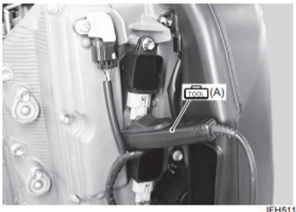
- Check the ignition timing while operating the engine in neutral gear at 1 000 r/min.
Ignition timing
Approx. 3° BTDC at 1 000 r/min
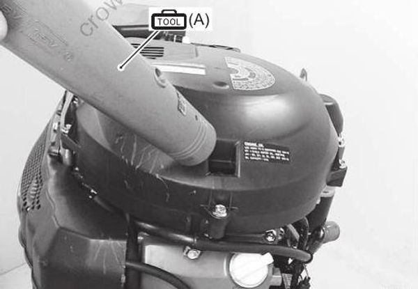
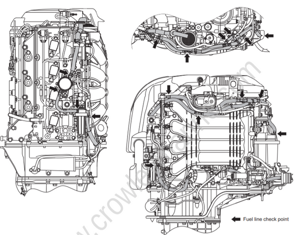
Breather Line and Fuel Line Inspection
Inspect breather line and fuel line
Initially after 20 hours (1 month) and every 100 hours (12 months)
If leakage, cracks, swelling or other damage is found, replace the breather hose and/or fuel line.
Low Pressure Fuel Filter Inspection
Inspect low pressure fuel filter / Initially after 20 hours (1 month) and every 100 hours (12 months)
Replace low pressure fuel filter / Every 400 hours or 2 years
If water accumulation, sediment, leakage, cracks or other damage is found, replace the low pressure fuel filter.
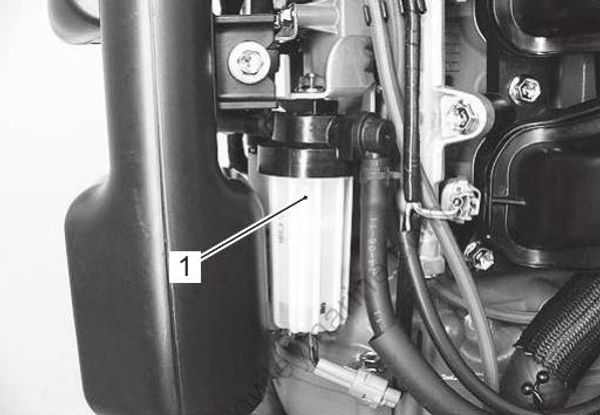
| 1. Low pressure fuel filter |
Gasoline is extremely flammable and toxic. It can cause a fire and can be hazardous to people and pets.
Always take the following precautions when servicing the fuel filter
• Stop the motor before cleaning the low pressure fuel filter.
• Be careful not to spill fuel. If you do, wipe it up immediately.
• Do not smoke, and keep away from open flames and sparks.
- Turn the engine off and allow it to cool.
Make sure that the main switch is in the OFF position.
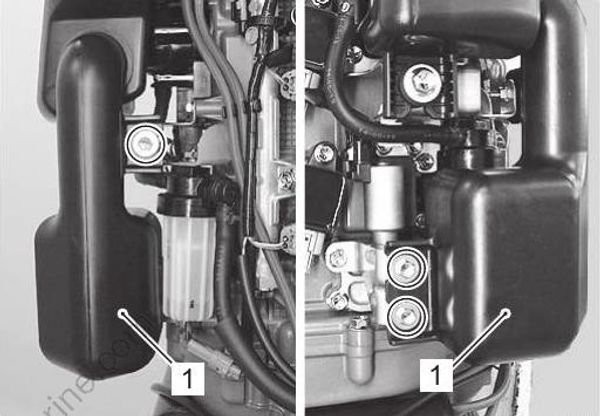
- Remove STBD lower side cover.
Refer to “Lower Side Cover Removal and Installation” in Section 2A (Page 2A-3).
- Remove the bolts securing resonator (1), then remove the resonator.
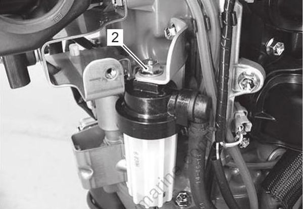
- Remove the nut (2) securing the low pressure fuel filter to filter bracket.
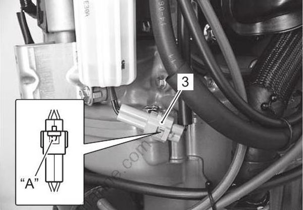
Improperly loosening the filter cup can cause switch lead wires damage.
• Be careful not to twist the switch lead wire when removing the filter cup.
• Disconnect the lead wire connector before removing the filter cup.
- Push the connector lock tab “A”, then disconnect the switch lead wire connector (3).
Place a rag under the filter before removal to catch any spilled fuel.
Separate the fuel filter cup (4) from the fuel filter body (5) by turning the fuel filter cup counterclockwise.
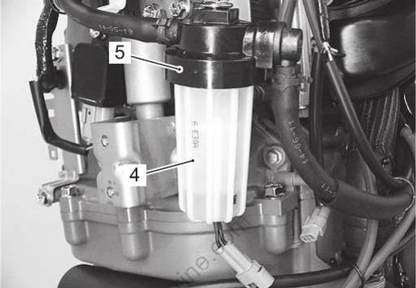
Drain fuel and water in the fuel filter cup (4) into a suitable container.
Pull out the filter element (6).
Inspect the filter element (6), O-ring (7) and seal ring (8) for damage.
If they are damaged, replace them.
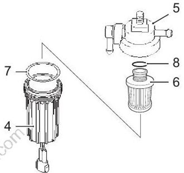
Wash the filter element (6) with clean solvent and dry it.
Assemble the seal ring (8) and filter element (6) in their original positions.
Verify that the O-ring (7) is in place in the top of the filter cup (4) and screw the filter cup back into place.
Connect the switch lead wire connector (3).
Reinstall the fuel filter and resonator.
Restart the engine and check that there are no leaks around the fuel filter.
High Pressure Fuel Filter Replacement
Replace high pressure fuel filter / Every 1000 hours
SUZUKI recommends that replacing the high pressure fuel filter every 1 000 operating hours.
For high pressure fuel filter replacement procedure, refer to “High Pressure Fuel Filter Removal and Installation” in Section 1G (Page 1G-30).
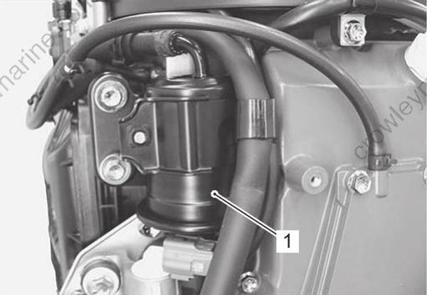
| 1. High pressure fuel filter |
Water Pump and Water Pump Impeller Inspection
Inspect water pump/pump impeller / Every 200 hours (12 months)
Replace water pump impeller / Every 300 hours (36 months)
- Remove the lower unit and water pump case.
Refer to “Water Pump Removal and Installation” in Section 3C (Page 3C-8).
Inspect water pump case, inner sleeve and under panel. Replace if wear, cracks, distortion or corrosion is found.
Inspect water pump impeller.
Replace if vanes are cut, torn or worn.
SUZUKI recommends that replacing the water pump impeller every 300 hours (36 months).
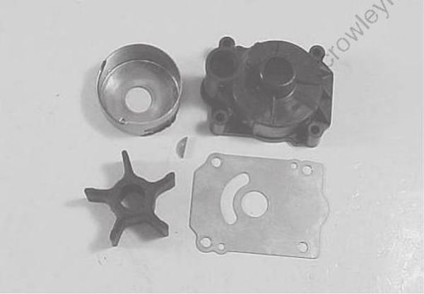
IEH511020034-01
- Assemble the water pump related items.
Refer to “Water Pump Removal and Installation” in Section 3C (Page 3C-8).
- Install the lower unit assembly.
Refer to “Lower Unit Removal and Installation” in Section 3C (Page 3C-6).
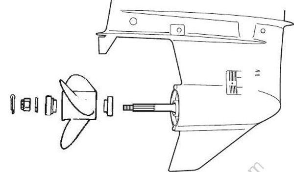
Propeller / Propeller Nut and Cotter Pin Inspection
Inspect propeller/propeller nut and cotter pin
Initially after 20 hours (1 month) and every 100 hours (12 months).
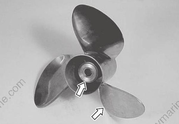
Inspect propeller for bent, chipped or broken blades. Replace propeller if damage noticeably affects operation.
Remove the propeller.
Refer to “Propeller Removal and Installation” in Section 3C (Page 3C-5).
Inspect propeller splines. Replace propeller if splines are worn, damaged or twisted.
Inspect propeller bush for slippage. Replace if necessary.
- Install the propeller and related parts.
Refer to “Propeller Removal and Installation” in Section 3C (Page 3C-5).
- Make sure that propeller nut is torqued to specification and cotter pin is installed securely.
Tightening torque
Propeller nut: 55 N·m (5.5 kgf-m, 40.0 lbf-ft)
Anode Inspection
Inspect anodes (External) / Initially after 20 hours (1 month) and every 100 hours (12 months)
Inspect anodes (Internal powerhead) / Every 100 hours (12 months)
If 2/3 of zinc anode has corroded away, replace anode. The anode should be periodically cleaned with a wire brush to ensure maximum effectiveness.
If anodes are not properly maintained, underwater aluminum surfaces (such as the lower unit) will suffer galvanic corrosion damage.
• Periodically inspect anodes to make sure they have not become detached.
• Do not paint anodes, as this will render them ineffective.
• Periodically clean anodes with a wire brush to remove any coating which might decrease their protective ability.
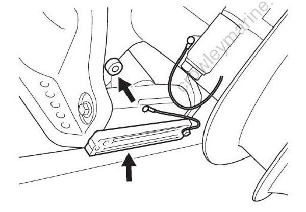
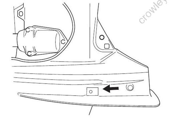
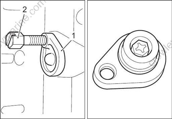
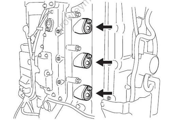
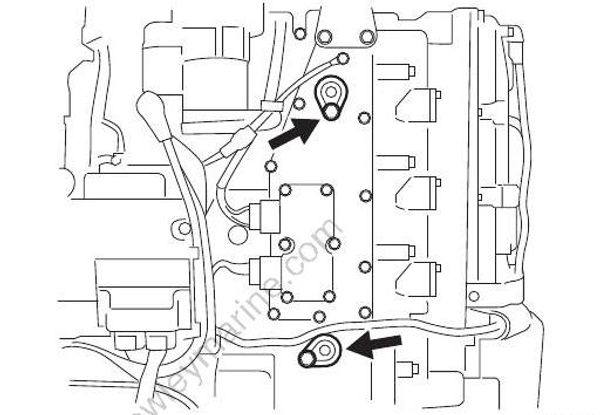
The anode cover (1) may be separated from the power unit body by inserting and turning a 10 mm bolt (2) to function as a screw jack.
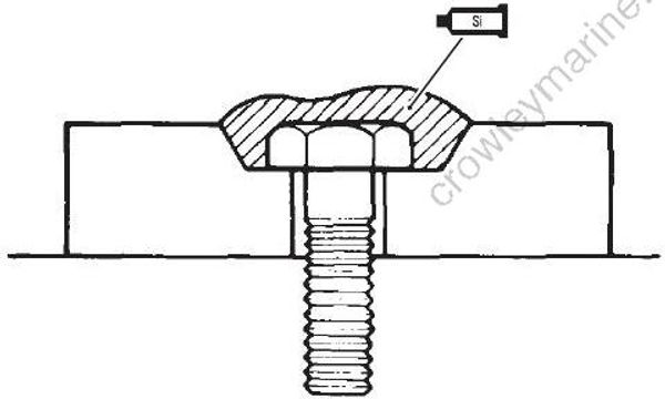
The anode securing bolt should be covered with suzuki silicone seal.
Sealant 93691–80030 (SUZUKI Silicone Seal (100 g))
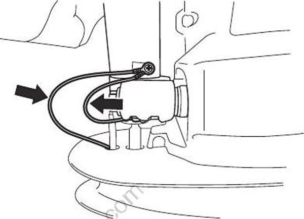
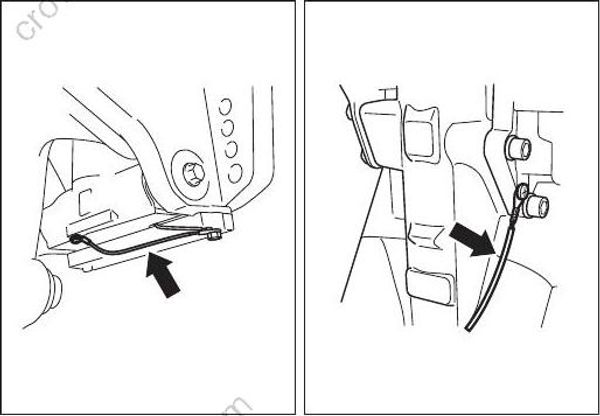
Bonding Wire Inspection
Inspect bonding wires / Initially after 20 hours (1 month) and every 100 hours (12 months)
If breakage or other damage is found on bonding wire, replace the wire.
If rust, corrosion or other damage is found on terminal, clean with cleaning solvent or replace the wire.
Battery Inspection
Inspect battery / Initially after 20 hours (1 month) and every 100 hours (12 months)
Failure to take proper precautions when handling the battery may cause severe injury.
Be sure to take the following precautions when handling the battery:
• Never expose the battery to open flames or electric sparks as batteries generate gas which is flammable and explosive.
• Do not place the battery near the fuel tank.
• Battery acid is poisonous and corrosive. Avoid contact with eyes, skin, clothing, and painted surfaces.
If you come in contact with battery acid, flush immediately with large amounts of water and seek immediate medical attention.
• Batteries should always be kept out of reach of children.
• When checking or servicing battery, disconnect the negative (black) cable.
Be careful not to cause a short circuit by allowing metal objects to contact the battery posts and motor at the same time.
• Wear approved eye protection.
Recommended battery
12 V 100 AH (360 kC) or larger
Refer to “Battery Requirement” in Section 0A (Page 0A 6).
Connecting Battery
Battery posts, terminals, and related accessories contain lead and lead compounds that may be hazardous.
Wash hands after handling.
Failure at the battery connection will cause incorrect operation of the engine control system.
Be sure to take the following precautions:
• Ensure battery cable connections are clean and secure.
• Be sure to use hexagon nuts to secure battery cables to the battery terminals to avoid loss of electrical power. Do not use wing nuts to secure the battery cables.
• Check the nuts periodically for proper tightness.
• Do not disconnect battery leads from the battery while the engine is running.
How to connect
Connect positive (+) terminal first.
Connect negative (–) terminal second.
Upon completion of connection, lightly apply grease to battery terminals.
Install the terminal cap on the positive battery terminal to prevent an accidental short circuit of battery terminals.
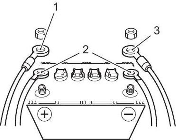
| 1. Red lead |
| 2. Sub battery cable |
| 3. Black lead |
How to disconnect
Disconnect negative (–) terminal first.
Disconnect positive (+) terminal second.
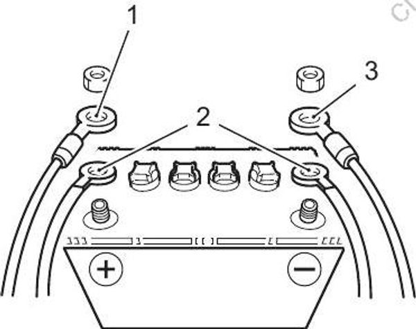
| 1. Red lead |
| 2. Sub battery cable |
| 3. Black lead |
Battery Solution Level Check
If you add diluted sulphuric acid to the battery after it has been initially serviced, you will damage the battery.
Never add diluted sulphuric acid to the battery after it has been initially serviced. Follow the battery manufacturer’s instructions for specific maintenance procedures.
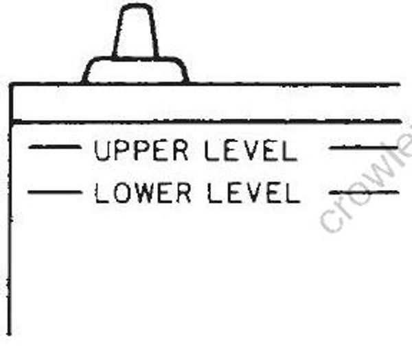
Battery solution level should be between UPPER level and LOWER level.
If level is low, add distilled water only.
Battery Solution Specific Gravity Check
Measure the specific gravity of battery solution using a hydrometer.
Battery solution specific gravity (Temperature)
1.28 (20 °C)
Special tool : 09900–28403 (Hydrometer)
Balancer Chain Replacement
Replace balancer chain
Every 1 600 hours
SUZUKI recommends replacing the balancer chain, chain tensioner and chain guide every 1 600 hours. For balancer chain replacement procedure, refer to “Timing Chain, Camshaft Sprocket, Balancer Chain Removal and Installation” in Section 1D (Page 1D-28).
Thermostat Inspection
Bolts and Nuts Inspection
Inspect bolts and nuts / Initially after 20 hours (1 month) and every 100 hours (12 months)
Check that all bolts and nuts listed below are tightened to their specified torque.
Refer to “Tightening Torque Specifications” in Section 0A (Page 0A-15).
Cylinder head cover bolts
Intake manifold bolts and nuts
Flywheel bolt
Power unit mounting bolts
Clamp bracket shaft nut
Lower mount bolts
Gearcase bolts
Propeller nut
Oil Pressure Check
Engine oil can be hot enough to burn you.
Do not remove the oil pressure gauge adapter when the engine is hot. Wait until engine cools.
Check the engine oil pressure periodically.
Check the engine oil level.
Remove STBD lower side cover.
Refer to “Lower Side Cover Removal and Installation” in Section 2A (Page 2A-3).
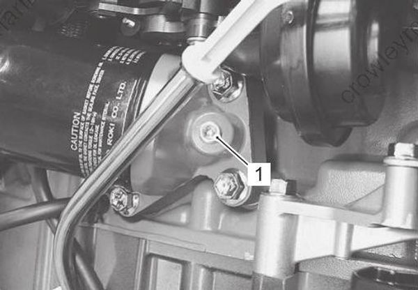
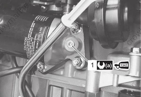
- Remove the plug (1) for oil pressure service port.
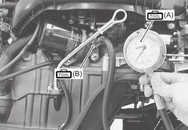
- Install oil pressure gauge in place of service port.
Special tool
(A): 09915–77311 (Oil pressure gauge)
(B): 09915–78211 (Oil pressure gauge adapter)
- Start engine and allow to warm up.
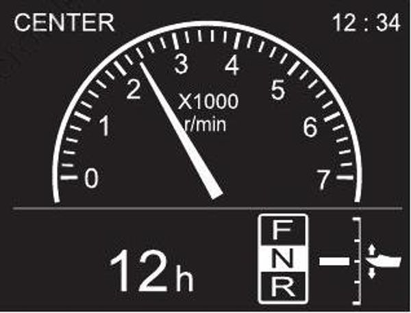
- After warming up, shift into forward gear and increase engine speed to 3 000 r/min., then compare pressure indicated on gauge to specifications.
The figure shown below is a guideline only, not an absolute service limit.
Oil pressure
400 – 600 kPa (4.0 – 6.0 kg/cm2, 57 – 85 psi.)
If oil pressure is lower or higher than specification, the following causes may be considered.
Low oil pressure
Clogged oil filter
Leakage from oil passages
Defective oil pump
Defective oil pressure regulator
Damaged O-ring
Combination of above items
High oil pressure
Using an engine oil of too high viscosity
Clogged oil passage
Clogged oil pressure regulator
Combination of above items
- Apply thread lock to the oil pressure service port plug (1).
Thread lock cement 99000–32050 (SUZUKI Thread Lock 1342 (50 g))
- Tighten the oil pressure service port plug (1) to specified torque.
Tightening torque
Oil pressure service port plug (a): 13 N·m (1.3 kgf-m, 9.5 lbf-ft)
- Reinstall STBD lower side cover.
Refer to “Lower Side Cover Removal and Installation” in Section 2A (Page 2A-3).
Cylinder Compression Pressure Check
The compression pressure reading of cylinder is good indicator of its internal condition.
The decision to overhaul the power unit is often based on the results of a compression test.
Periodic maintenance records kept at your dealership should include compression readings for each maintenance service.
Start engine and allow to warm up, then shut engine off.
Disconnect all fuel injector connectors at fuel injector.
Remove all spark plugs.
Refer to “Spark Plug Removal and Installation” (Page 0B-7).
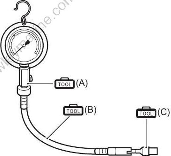
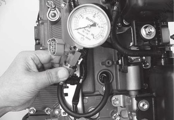
- Install compression gauge hose attachment into spark plug hole, then connect compression gauge hose to gauge hose attachment and compression gauge.
Special tool
(A): 09915–64512 (Compression gauge)
(B): 09915–64530 (Compression gauge hose)
(C): 09915–64550 (Compression gauge
Turn the main switch “ON”.
Confirm the select switch LED lights.
If not, depress the “SELECT” button on switch panel.
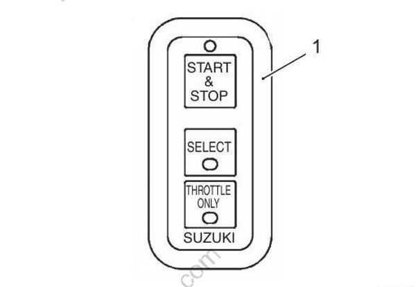
| 1. Switch panel |
Depress the “THROTTLE ONLY” button.
Move and hold remote control lever on throttle full open position.
While cranking engine with starter motor, note maximum compression pressure reading on gauge for each cylinder.
Figures shown are guidelines only, not absolute service limits.
Cylinder compression pressure
Standard: 1 100 – 1 700 kPa (11 – 17 kgf/cm2, 156 – 242 psi.)
Cylinder compression pressure max. difference between cylinders
100 kPa (1.0 kgf/cm², 14 psi.)
Low compression pressure can indicate one or more of following:
Excessively worn cylinder wall
Worn piston or piston rings
Stuck piston rings
Poor seating of valves
Ruptured or otherwise damaged cylinder head gasket
- Reinstall parts removed earlier.
