

Fuel / Water Hose Routing
Precautions
Precautions for Fuel / Water Hose Routing
Refer to “General Precautions” in Section 00 (Page 00-1) and “Precautions on Fuel System Service” in Section 1G (Page 1G-1).
Schematic and Routing Diagram
Fuel Hose Routing
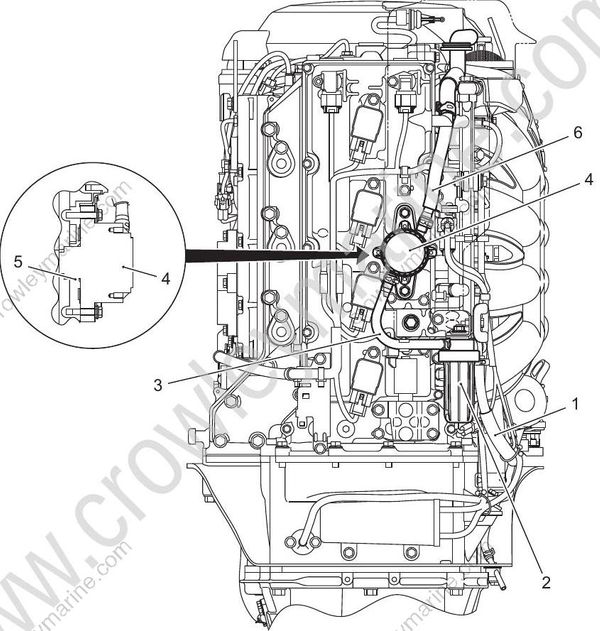
- Fuel hose (fuel connector to low pressure fuel filter)
- Low pressure fuel filter / water detection switch
- Fuel hose (low pressure fuel filter to low pressure fuel pump)
- Low pressure fuel pump
- O-ring
- Fuel hose (low pressure fuel pump to 2-way union)
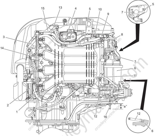
- Fuel hose (fuel connector to low pressure fuel filter)
- Low pressure fuel filter/water detection switch
- Fuel hose (low pressure fuel pump to 2-way union)
- 2-way union
- Fuel hose (2-way union to fuel vapor separator)
- Fuel vapor separator
- Fuel hose (fuel vapor separator to high pressure fuel filter)
- High pressure fuel filter
- Fuel hose (high pressure fuel filter to 3-way union)
- 3-way union
- Fuel cooler
- Fuel hose (fuel cooler to fuel vapor separator)
- Fuel hose (3-way union to fuel delivery pipe)
- Fuel delivery pipe
- Breather hose
- Fuel drain hose
“a”: 40 mm (1.57 in.) or more
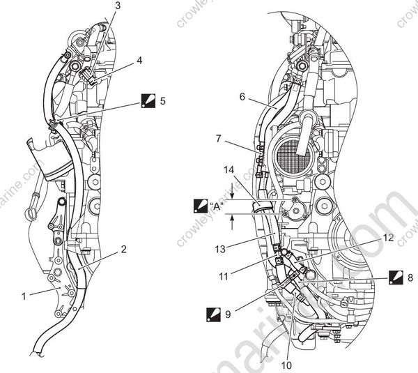
- Clutch holder
- Fuel hose (fuel connector to low pressure fuel filter)
- Fuel injector
- Fuel injector cushion
- Clamp: Install the fuel hose to clamp at mark point of hose.
- Fuel hose (low pressure fuel pump to 2-way union)
- 2-way union
- Fuel hose (2-way union to fuel vapor separator):Pass the fuel hose (2-way union to fuel vapor separator) so as not to be squashed between MAP sensor and fuel hose guard.
- Clamp: Place the clamp onto the mark position of fuel hose. Make sure fuel hose is away from 3-way union hose clip.
- Fuel hose (high pressure fuel filter to 3-way union)
- 3-way union
- Fuel hose (3-way union to fuel cooler)
- Fuel hose (3-way union to fuel delivery pipe)
- Clamp
“A”: Place the clamp (14) in this range.
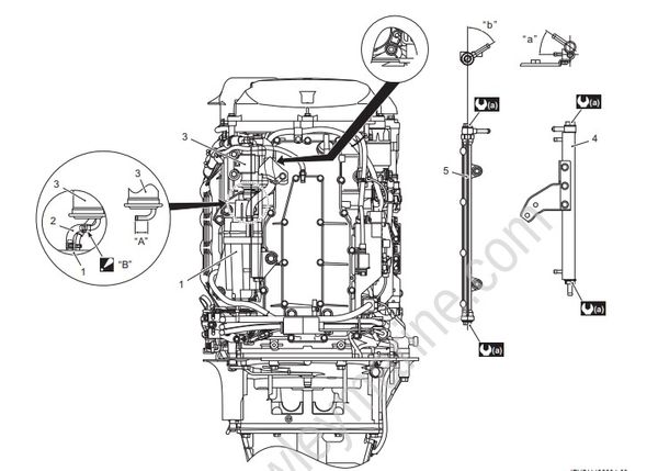
- Fuel vapor separator
- Fuel hose (fuel vapor separator to high pressure fuel filter)
- High pressure fuel filter
- Fuel cooler
- Fuel delivery pipe
“A”: Unpainted area
“B”: Insert the fuel hose (fuel vapor separator to high pressure fuel filter) to high pressure fuel filter union unpainted area.
“a”: 35°
“b”: 58°
a : 35 Nm (3.5 kgf-m, 25.3 lbf-ft)
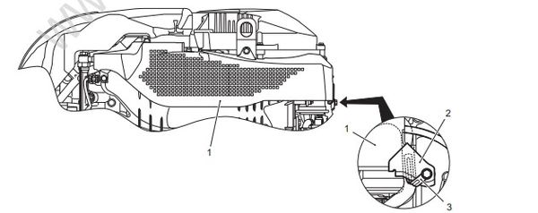
- Fuel hose guard
- Fuel hose guard guide
- Clamp
Evaporation Hose Routing
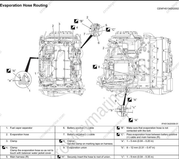
- Fuel vapor separator
- Evaporation hose
- Clamp
- Clamp: Clamp the evaporation hose so as not to touch with balancer water jacket cover.
- Main harness (R)
- Battery positive (+) cable
- Battery negative (–) cable
- Clamp: Set the clamp on marking tape on harness.
- Evaporation union
“A”: Securely insert the hose to root of union.
“B”: Make sure that evaporation hose is not contacted with the bolt.
“C”: Pass evaporation hose between battery positive (+) cable and main harness (R).
“a”: 1 – 5 mm (0.04 – 0.20 in)
“b”: 8 – 12 mm (0.31 – 0.47 in)
“c”: 1 – 9 mm (0.04 – 0.35 in)
Water Hose Routing
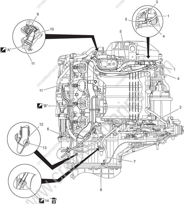
- Water hose (balancer water jacket cover to 3-way union)
- Water hose (3-way union to fuel cooler)
- Water hose (fuel cooler to 3-way union)
- 3-way union
- Water hose (3-way union to thermostat cover)
- Water hose (engine holder cover to cylinder block)
- Water hose (cylinder block to water indicator)
- Water indicator
- Thermostat
- Thermostat cover
- Water return hose
- Water return union
- O-ring
- O-ring: Apply engine oil to O-ring.
“A”: Connect the water return hose to thermostat cover with the painting mark side “A” up.
“B”: Place the clamp between fuel injector #3 and low pressure fuel filter bracket.
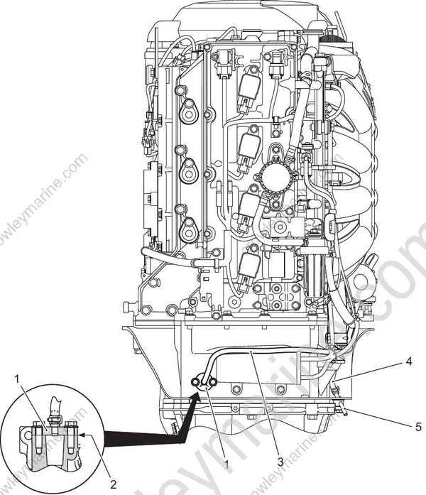
- Engine holder cover
- Gasket
- Water hose (engine holder cover to cylinder block)
- Water hose (cylinder block to water indicator)
- Water indicator
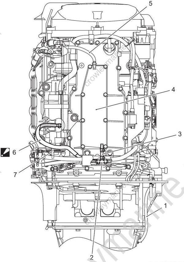
- Water hose (oil pan to 3-way union)
- 3-way union
- Water hose (3-way union to balancer water jacket cover)
- Balancer water jacket cover
- Water hose (balancer water jacket cover to 3-way union)
- Water hose (3-way union to fuel cooler): Route water hose (3-way union to fuel cooler) outside of the drain union of fuel vapor separator.
- Fuel vapor separator drain union
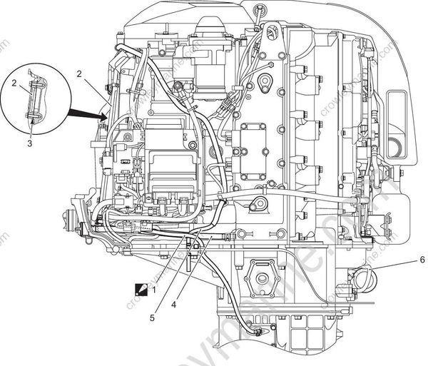
- Water hose (oil pan to 3-way union): Route water hose (oil pan to 3-way union) outside of the evaporation hose.
- Balancer water jacket cover
- Gasket
- Water flush hose
- Evaporation hose
- Water hose (engine holder cover to cylinder block)
