

ABBREVIATIONS USED IN THIS MANUAL
Units of Measurement
| A | Amperes |
| amp-hr | Ampere hour |
| fl. oz. | fluid ounce |
| ft. lbs. | foot pounds |
| HP | horsepower |
| in. | inch |
| in. Hg | inches of mercury |
| in. lbs. | inch pounds |
| kPa | kilopascals |
| ml | milliliter |
| mm | millimeter |
| N·m | Newton meter |
| P/N | part number |
| psi | pounds per square inch |
| RPM | revolutions per minute |
| °C | degrees Celsius |
| °F | degrees Fahrenheit |
| ms | milliseconds |
| µs | microseconds |
| Ω | Ohms |
| V | Volts |
| VAC | Volts Alternating Current |
| VDC | Volts Direct Current |
List of Abbreviations
| ABYC | American Boat & Yacht Council |
| ATDC | after top dead center |
| AT | air temperature sensor |
| BPS | barometric pressure sensor |
| BTDC | before top dead center |
| CCA | cold cranking amps |
| CPS | crankshaft position sensor |
| EMM | Engine Management Module |
| ICOMIA | International Council of Marine Industry Associations |
| MCA | marine cranking amps |
| MWS | modular wiring system |
| NMEA | National Marine Electronics Assoc. |
| NTC | negative temperature coefficient |
| PTC | positive temperature coefficient |
| ROM | read only memory |
| S.A.F.E.™ | speed adjusting failsafe electronics |
| SAC | start assist circuit |
| SAE | Society of Automotive Engineers |
| SYNC | synchronization |
| TDC | top dead center |
| TPS | throttle position sensor |
| WOT | wide open throttle |
| WTS | water temperature sensor |
MODEL DESIGNATION

MODELS COVERED IN THIS MANUAL
This manual covers service information on all 79 cubic inch, 3-Cylinder Evinrude E-TEC ® models.
| Model Number | Shaft | Color | Gearcase |
|---|---|---|---|
| E75DPLSCB | 20” | BL | “S” |
| E75DSLSCS | 20” | WH | “S” |
| E90DPLSCB | 20” | BL | “S” |
| E90DSLSCM | 20” | WH | “S” |
| E90DPXSCB | 25” | WH | “O” |
| E90WDELSCS | 20” | BL | “S” |
| E90WDEXSCS | 25” | WH | “O” |
Identifying Model and Serial Numbers
Outboard model and serial numbers are located on the swivel bracket and on the powerhead.
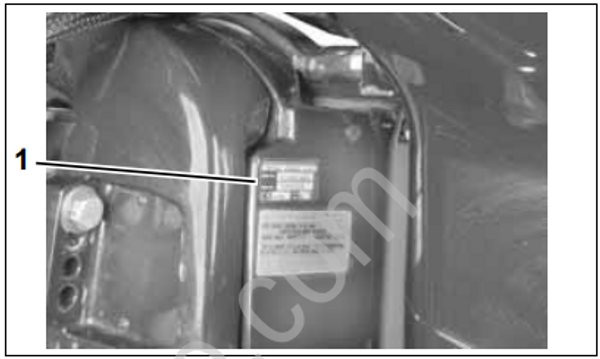
002147
- Model and serial number
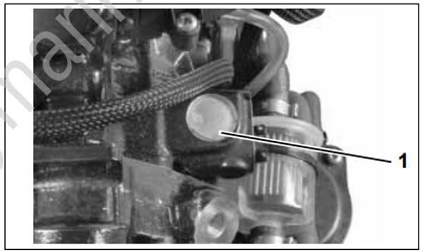
002226
- Serial number
SERVICE SPECIFICATIONS
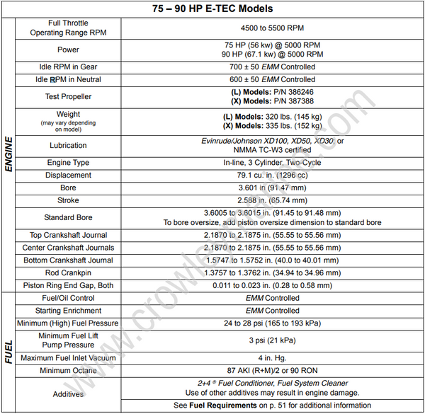
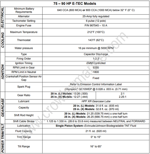
STANDARD TORQUE SPECIFICATIONS
| Size | In. Lbs. | Ft. Lbs. | N·m |
|---|---|---|---|
| No. 6 | 7–10 | 0.58–0.83 | 0.8–1.1 |
| No. 8 | 15–22 | 1.25–1.83 | 1.7–2.5 |
| No. 10 | 24–36 | 2–3 | 2.7–4.0 |
| No. 12 | 36–48 | 3–4 | 4.0–5.4 |
| 1/4 in. | 60–84 | 5–7 | 7-9.5 |
| 5/16 in. | 120–144 | 10–12 | 13.5–16.5 |
| 3/8 in. | 216–240 | 18–20 | 24.5–27 |
| 7/16 in. | 336–384 | 28–32 | 38–43.5 |
IMPORTANT: These values apply only when a specific torque for a specific fastener is not listed in the appropriate section. When tightening two or more screws on the same part, DO NOT tighten screws completely, one at a time.
Torque wrench tightening specifications must be strictly adhered to. Replace any locking fastener (locknut or patch screw) if its locking feature becomes weak. Definite resistance to turning must be felt when reusing a locking fastener. If replacement is specified or required because the locking fastener has become weak, use only authorized Evinrude/ Johnson Genuine Parts.
PRODUCT REFERENCE AND ILLUSTRATIONS
BRP US Inc. reserves the right to make changes at any time, without notice, in specifications and models and also to discontinue models. The right is also reserved to change any specifications or parts, at any time, without incurring any obligation to equip same on models manufactured prior to date of such change. Specifications used are based on the latest product information available at the time of publication.
The continuing accuracy of this manual cannot be guaranteed.
All photographs and illustrations used in this manual may not depict actual models or equipment, but are intended as representative views for reference only.
Certain features or systems discussed in this manual might not be found on all models in all marketing areas.
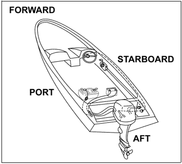
All service technicians must be familiar with nautical orientation. This manual often identifies parts and procedures using these terms.
006411
Nautical Orientation
