

Inspection
Carefully examine propeller and outboard for the following:
• Damaged blades and signs of propeller cavitation (burned paint, etc.)
• Spun or overheated inner hub
• Worn or twisted splines and inadequate lubricant
• Damaged or missing converging ring (if applicable)
• Damage to outer hub area
• Worn, missing, or incorrect thrust washer and spacer
• Correct size and style
• Check for bent or damaged propeller shaft and twisted splines
Refer to Propeller Hardware Installation on p. 288.
When servicing the propeller, always shift the outboard to NEUTRAL, turn the key switch OFF, and disconnect the battery positive (+) cable so the outboard cannot be started accidentally
Propeller Selection
Selection of the wrong propeller could reduce engine service life, affect boat performance, or cause serious damage to the powerhead
Water testing with various propeller designs and sizes is the best method of propeller selection.
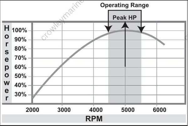
The correct propeller, under normal load conditions, will allow the engine to run near the midpoint of the RPM operating range at full throttle. Refer to SERVICE SPECIFICATIONS on p. 10.
008329
If the propeller blades have too much pitch, the engine will operate below its normal range at full throttle. Power will be lost, and powerhead damage could occur. If the propeller blades have too little pitch, the engine will operate above its normal range and damage from over speeding could occur.
When selecting a propeller, consider the following:
• Use an accurate tachometer to determine the engine’s full-throttle RPM.
• The outboard should be trimmed for top speed.
• Select a propeller that suits the customer’s application and allows the engine to run near the midpoint of the full-throttle operating range when the boat has a normal load.
• Occasionally, one propeller will not cover a wide range of boat applications — water skiing to high speed performance boating. In such cases, it might be necessary to have a propeller for each situation.
• Refer to the Evinrude/Johnson Genuine Parts and Accessories Catalog for propeller styles and sizes.
• Right-hand propellers are considered standard rotation propellers. When propelling a boat forward, the propeller rotates in a right-hand (clockwise) direction as viewed from the rear.
• Left-hand propellers are considered counterrotation propellers. When propelling a boat forward, the propeller rotates in a left-hand (counterclockwise) direction as viewed from the rear
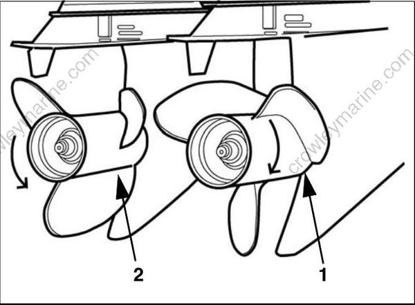
- Right-hand rotation (clockwise)
- Left-hand rotation (counterclockwise)
000033
For dual-outboard installations, always check to be sure propellers are installed
Propeller Hardware Installation
To prevent accidental starting while servicing, twist and remove all spark plug leads.
IMPORTANT: Depending on propeller style, different thrust bushings, spacers, and cotter pin keepers are used. See the Evinrude/Johnson Genuine Parts and Accessories Catalog for correct propeller hardware.
Apply Triple Guard grease to the entire propeller shaft before installing the propeller.
Install thrust bushing onto propeller shaft with taper of bushing matching taper of shaft.
If installing a propeller with an interchangeable hub, assemble the propeller following instructions provided with the propeller.
Align splines of propeller and shaft. Push propeller until seated on the thrust bushing.
Install the spacer over the propeller shaft splines.
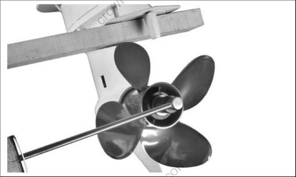
Wedge a block of wood between propeller blade and the anti-ventilation plate
001992
Install the propeller nut and tighten to a torque of:
• With Keeper – 70 to 80 ft. lbs. (95 to 109 N·m)
• Without Keeper – 120 to 144 in. lbs. (13.6 to 16.3 N·m)
If cotter pin holes in the nut (without keeper) and shaft do not align, tighten further. Do not loosen. Install keeper (if applicable). Install new cotter pin
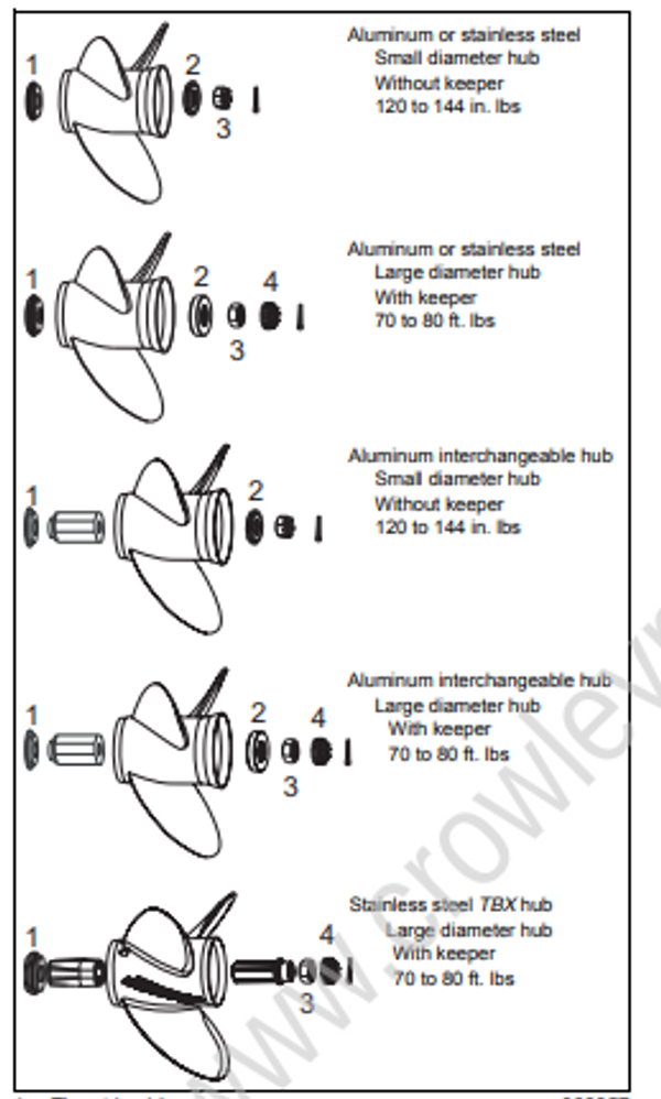
- Thrust bushing
- Spacer
- Propeller nut
- Keeper
008057
IMPORTANT: After installation, make sure outboard is in NEUTRAL and carefully spin propeller. Propeller must turn freely and should not spin off center. If propeller appears to wobble, check for possible bent propeller shaft.
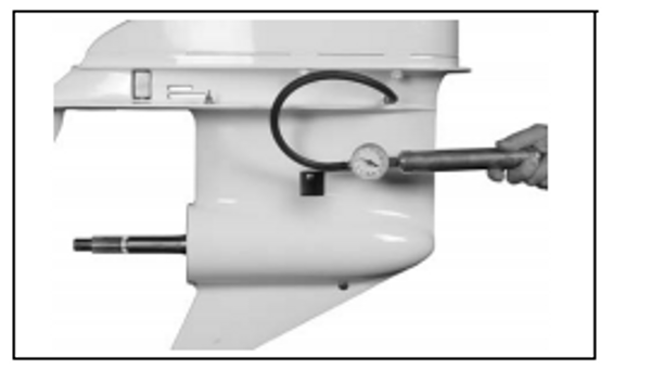
GEARCASE LEAK TEST
Drain lubricant before testing.
Use Gearcase Pressure Tester, P/N 507977. Install lubricant drain/fill plug and seal, thread pressure test gauge fitting and seal in lubricant
level hole.
Pressurize 3 to 6 psi (21 to 42 kPa).
If pressure gauge indicates leakage, submerge the gearcase in water to determine source of leak. If the gauge does not indicate leakage, increase pressure to 16 to 18 psi (110 to 124 kPa). Check for leaks.
Make necessary repairs and repeat test.
Install Gearcase Vacuum Tester, P/N 507982. Apply 3 to 5 in. of vacuum (76 to 127 mm) Hg. with pump.
If vacuum gauge indicates leakage, apply oil around suspected seal. If leak stops or oil is drawn in, seal is defective.
Repeat test, gearcase must hold minimum of 15
in. vacuum (381 mm) Hg.
002388
IMPORTANT: After installation, make sure out board is in NEUTRAL and carefully spin propeller. Propeller must turn freely and should not spin off center. If propeller appears to wobble, check for possible bent propeller shaft.
