IGNITION OUTPUT TESTS
DANGER
The electrical system presents a serious shock hazard. Allow outboard to sit for two minutes after running before handling capacitor or 55 V electrical components. Failure to handle capacitor properly can result in uncontrolled electrical discharge and possible electrical shock to humans. DO NOT handle primary or secondary ignition components while outboard is running or flywheel is turning.
Use the Evinrude Diagnostics software Occurred Faults screen to check for current service codes before troubleshooting. Correct any problems and clear the codes FIRST.
Required Ignition Systems
Following is a complete list of circuits required for ignition output:
Stop Circuit
- Black/yellow wire NOT grounded (emergency stop switch lanyard in place).
Neutral Switch
- Powerhead mounted neutral switch provides a switched ground circuit to EMM. The circuit enables specialized control functions such as neutral start protection and RPM limiting in NEUTRAL.
Stator Output Voltage
- Provides A/C voltage to EMM J2 connector: Outboard cranking, typical range is 20-40 VAC (AC output voltage is related to cranking RPM); Outboard running, approximately 55 VAC.
EMM
- Controls ignition grounds, injector grounds, and engine timing.
Crankshaft Position Sensor
Provides EMM with input.
Outboard cranking speed exceeds 300 RPM and a steady CPS signal is generated.
Alternator Output/System Voltage
- System voltage from EMM (white/red) provides 55 VDC to the high pressure fuel pump, the oil injection pump, the fuel injectors, and the ignition coils.
Capacitor
Connected to 55 V circuit (white/red) to stabilize current on 55 V circuit
Negative terminal of capacitor must be grounded.
Ignition Coil
Primary circuits are powered by system (55 V) voltage
EMM provides control signal to ignition coil
Output from ignition coil secondary winding and high tension spark plug wire.
Wiring Inspection
Visually inspect all wiring, connections, and grounds.
Use a digital ohmmeter to test resistance on all ground circuits and connections. Ohmmeter readings should be approximately 0.0 W.
Check that all engine wire harness grounds have continuity to the cylinder/crankcase.
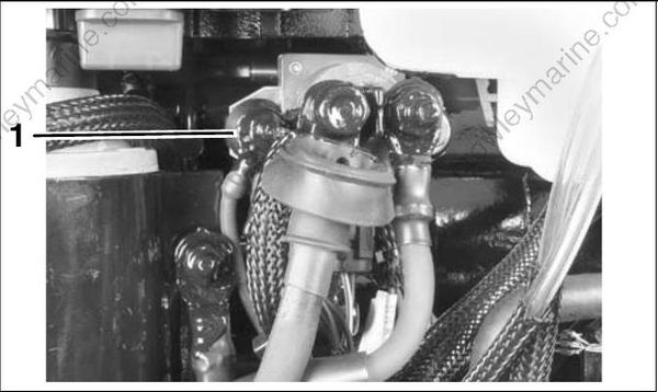
- Main engine harness ground
Clean or repair all ground circuits, wiring, and connections as needed.
Crankshaft Position Sensor (CPS) Test
When the CPS is working properly, EMM LED 2 turns on while the outboard is being started.
Use the Evinrude Diagnostics software CPS Sync and engine RPM displays to confirm a valid CPS signal while the outboard is cranking or running. An RPM display higher than zero indicates a CPS signal to the EMM.
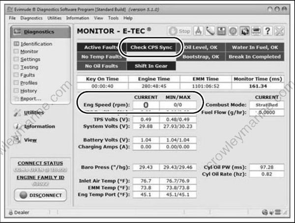
Engine RPM and CPS Sync displays
If the Monitor screen says “Check CPS Sync,” refer to Crankshaft Position Sensor (CPS) Test on p. 99.
System Voltage Test
The ignition system is powered by the 55 V system.
Use the Evinrude Diagnostics software Monitor screen to check system voltage.
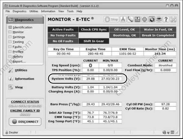
Monitor Screen, System voltage
Results:
EMM ON (not running) approximately 1 V less than battery voltage, system voltage is GOOD.
EMM ON (not running) no voltage, check 12 V power to EMM. Repair connection or wiring.
RUNNING 55 V ± 2, system voltage is GOOD.
RUNNING less than 55 V ± 2, check stator output to EMM. Repair connection or wiring. Possible faulty stator or EMM. Refer to STATOR TESTS on p. 101.
IMPORTANT: The EMM must be ON for voltage to be present on the system voltage (55 V) circuit. Power is normally supplied to the EMM when the key switch is turned ON. The EMM is also turned ON when it begins to receive AC voltage from the stator while the outboard is being cranked. On a non-running rope start engine, power is supplied to the EMM by Diagnostic Power Supply Tool, P/N 587005.
Static Ignition Test
Perform the static ignition test using Evinrude Diagnostics software and an inductive timing light.
IMPORTANT: DO NOT perform static tests using Diagnostic Power Supply Tool, P/N 587005, with internal 9 volt batteries only. This will produce false results. Refer to Communication on p. 67.
IMPORTANT: DO NOT use a spark checker tool. Radio Frequency Interference (RFI) generated by the arcing current can cause erratic EMM operation.
The outboard must NOT be running and the emergency stop switch lanyard must be installed.
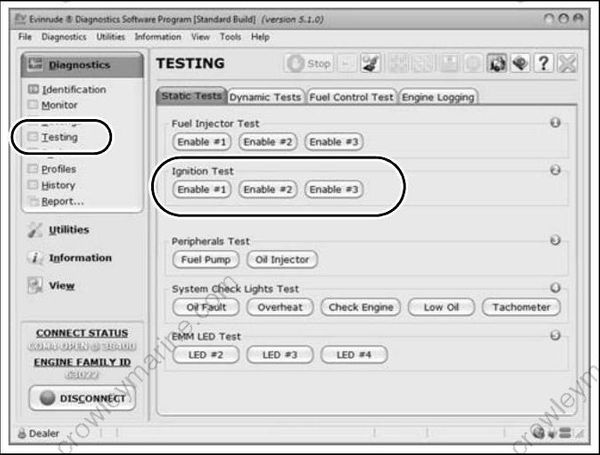
Static Tests Screen
Connect timing light pickup to the secondary circuit (spark plug lead) of the cylinder being tested. Activate test and observe timing light strobe for consistent flash.
IMPORTANT: This test is operating the ignition coil with 12 V battery power on the system voltage (55 V) circuit. An inductive probe with low sensitivity may not be able to detect the signal.
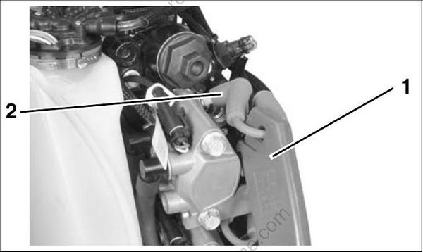
- Timing light pick-up
- Spark plug lead
Results:
No spark on one or more cylinders:
Inspect or replace spark plugs
Refer to Ignition Control Circuit Tests on p. 87
Refer to Ignition Coil Tests on p. 87
Steady spark on all cylinders:
- Refer to Running Ignition Tests on p. 86 and DYNAMIC TESTS on p. 80.
Running Ignition Tests
Use Evinrude Diagnostics Software to monitor system voltage (55 V).
Voltage readings at a specific speed (RPM) should be steady
Refer to System Voltage Test on p. 84.
Use an inductive timing light to monitor the spark signal through each of the secondary circuit (spark plug lead) wires.
Start outboard and observe timing light strobe. Look for a consistent flash and only one flash per revolution. The strobe of the timing light should be the same for each cylinder.
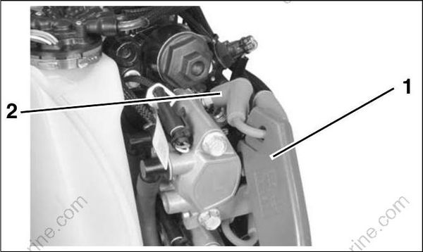
- Timing light pick-up
- Spark plug lead
Results:
Steady voltage and strobe, engine misfires:
Inspect or replace spark plugs
Refer to FUEL DELIVERY TESTS on p. 88
Check for internal engine damage.
Steady voltage, erratic strobe, engine misfires:
Inspect or replace spark plugs
Check CPS air gap and resistance.
Refer to Ignition Control Circuit Tests on p. 87
Refer to Ignition Coil Tests on p. 87. Voltages fluctuate, engine misfires:
Inspect battery and connections
Test capacitor and all ground connections.
Refer to System Voltage Test on p. 84
Refer to Ignition Control Circuit Tests on p. 87
Refer to Ignition Coil Tests on p. 87.
IMPORTANT: If a running problem occurs at about 1200 RPM, the outboard may be in S.A.F.E. Refer to S.A.F.E. WARNING SYSTEM on p. 66.
Ignition Control Circuit Tests
Use a digital multimeter to test the following:
System voltage supply to ignition coil.
Ignition control signal from EMM.
Engine harness resistance.
Disconnect ignition coil connector.
Supply voltage test:
Use an appropriate adapter to connect the red meter lead to pin 3 (white/red) of the engine harness connector and the black lead to ground. With EMM ON, voltage should be approximately 1 V less than battery voltage.
Control signal test:
Set meter to the Hz scale to check ignition control signal.
Use an appropriate adapter to connect the red meter lead to pin 2 (orange) of the engine harness connector and the black lead to ground. Activate diagnostics software Static Ignition test and observe meter for consistent reading (approximately 2 Hz).
If control signal is present, connect black meter lead to pin 1 (black) and repeat test to confirm harness ground.
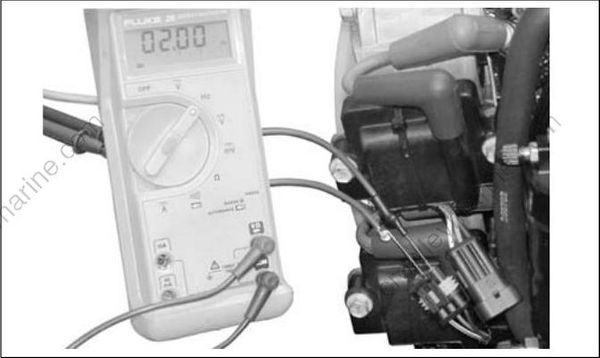
Harness resistance test:
If control signal is NOT present, calibrate multimeter to low ohms scale. Use appropriate adapters on meter leads to avoid damaging harness connectors.
With EMM OFF, remove the EMM J1-B connector and test the continuity of each ignition control circuit (orange). Check resistance between J1-B connector and ignition coil connector. Refer to engine wiring diagram.
If circuits test good, replace EMM.
Ignition Coil Tests
There are no simple ignition coil tests available. Before replacing an ignition coil, be sure:
55 V is supplied to the white/red wire of the ignition coil connector
A control signal is present on the orange wire of the ignition coil connector. Refer to Ignition Control Circuit Tests on p. 87.
The black wire of the ignition coil connector pro vides continuity to ground.
The secondary spark plug lead provides continuity.
If all of the above tests are good, and a cylinder does not have spark, replace the ignition coil with a known good coil.
Capacitor Test
IMPORTANT: Make sure the capacitor is dis charged before testing. Make a momentary connection between the two terminals to ground any stored energy.
Remove capacitor from electrical harness.
Use an ohmmeter set on the high ohms scale to test the capacitor. Connect the meter leads to the capacitor terminals:
If the capacitor is working correctly, it will store energy from the meter. The resistance reading will increase until it goes to (nearly) infinity.
If the capacitor is shorted, the reading will immediately show full continuity.
If there is an open circuit in the capacitor, the meter will show no continuity.
If the resistance reading starts as a negative number, or the reading goes down in value, the capacitor already retains some stored energy. Ground the capacitor and test again.