Tachometer Pulse Setting (System Check)
Confirm accuracy of tachometer reading.
• Adjust dial on back of tachometer to required setting (the outboard should not be running).
| Outboard Model | Tachometer Setting |
|---|---|
| 40–90 HP | 6 Pulse or 12 Pole |
Water Pump Overboard Indicator
A steady stream of water should flow from the overboard indicator.
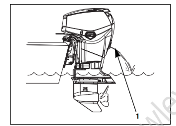
- Water pump overboard indicator 008469
Operating Temperature
An outboard run at idle speed should achieve a temperature based on the engine’s thermostatic control. In general, the powerhead temperature should reach at least 104°F (40°C) after five minutes of idling. Check that the powerhead reaches
idle temperature. Refer to SERVICE SPECIFICATIONS AB MODELS on p. 12.
Idle Speed
Make sure the outboard idles within the specified idle RPM range. If the outboard is run on a flushing device, the idle speed and quality may not be representative of actual in water use.
COOLING SYSTEM
Regularly inspect cooling system components for
corrosion, damage, leaks, or restrictions:
• water intake screens
• water pump
• all internal water passages
• thermostats
• all external water hoses and fittings
• vapor separator cooling passages and fittings
• EMM cooling passages and fittings
• overboard water pressure indicator.
Water Intake Screens
Inspect condition of water intake screens. Clean or replace as needed.
Confirm function of overboard water pressure indicator
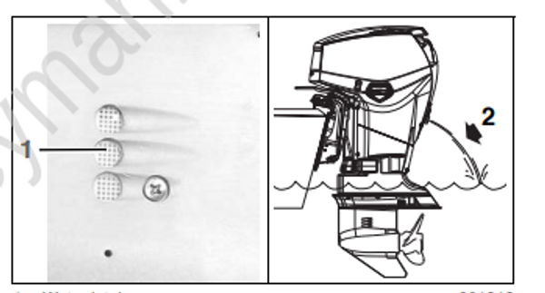
- Water intake screen
- Overboard indicator
001212
008470
Engine Flushing
Flush the outboard with fresh water following each use in brackish, salt, or polluted water to minimize the accumulation of scale and silt deposits in cooling system passages.
The outboard can be flushed on the trailer or at dockside; running or not running.
IMPORTANT: The outboard must be located in a well ventilated area with appropriate ground drainage during the flushing procedure.
Keep water inlet pressure between 20 to 40 psi (140 to 275 kPa).
Flushing — Outboard Running
To prevent injury from contact with rotating propeller, remove the propeller before flushing.
Place outboard in VERTICAL (DOWN) position in a well ventilated area.
Thread garden hose into flushing port.
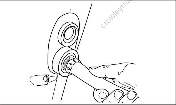
002024
Turn water supply on.
Run outboard at IDLE only until full operating temperature is reached.
Leave the outboard in VERTICAL (DOWN) position long enough for the powerhead to drain completely.
Reinstall propeller.
Flushing — Outboard Not Running
Outboard can be in VERTICAL (DOWN) or TILTED (UP) position.
Thread garden hose into flushing port.
Turn water supply ON.
Flush outboard for at least five minutes.
Turn off water supply and remove garden hose.
Leave the outboard in VERTICAL (DOWN) position long enough for the powerhead to drain completely
Running the Outboard Using a Hose and Flushing Adapter
To prevent injury from contact with rotating propeller, remove the propeller before running engine with a flushing adapter.
A flushing adapter may be used to provide cooling water when running the outboard to:
• Flush the engine
• Run for an extended period of time, such as when performing diagnostic work
• Run the engine on a dynamometer
• Prepare the outboard for storage.
IMPORTANT: The outboard must be located in a well ventilated area with appropriate ground drainage.
Keep water inlet pressure between 20 to 40 psi (140 to 275 kPa).
Be sure water supply is sufficient to run the engine above idle speed. Water Supply Requiremts.
| Model | Water Flow @ WOT |
|---|---|
| 40–65 HP | 4 to 6.5 GPM 1 (15 to 24 LPM 2) |
| 75–90 HP | 7.5 to 9 GPM (28 to 34 LPM) |
- GPM: Gallons per minute 2. LPM: Liters per minute
Install flushing adapter onto gearcase water inlet screens.
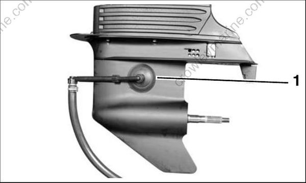
- Flushing adapter 008342
A steady stream of water should flow from the overboard indicator while the engine is running.
Monitor engine water pressure gauge when:
• Engine speed is above 3000 RPM
• Running engine on a dynamometer.
Refer to SERVICE SPECIFICATIONS AB MODELS on p. 12 for water pressure requirements
Engine will overheat if normal water pressure is not maintained. Temporarily install an engine water pressure gauge if not equipped with one.