Powerhead Mounting – 2-Cylinder Models
Apply Permatex No. 2 to both sides of a new base gasket around the exhaust port only. Install gasket on exhaust housing. To ensure proper sealing, mating surfaces must be clean and dry.
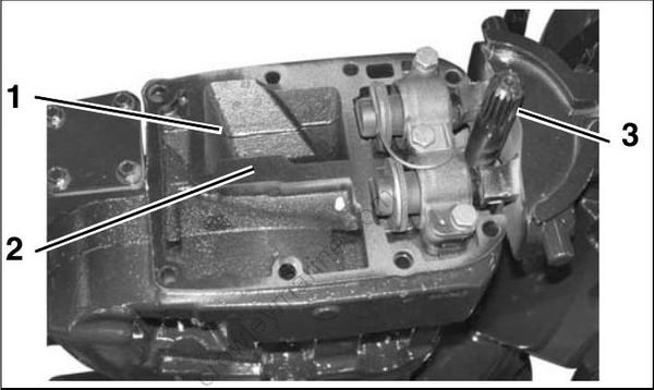
- Exhaust port
- Clean surface
- Moly Lube
004972
Coat the driveshaft splines with Moly Lube. Do not apply lubricant to end of driveshaft.
Use Lifting Fixture, P/N 396748, and hoist to slowly lower powerhead onto exhaust housing. If necessary, rotate flywheel in a clockwise direction to align crankshaft and driveshaft splines.
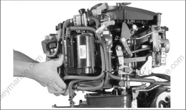
002269
Apply Triple-Guard grease to the threads, and Gasket Sealing Compound to the shank of the powerhead screws.
Loosely install all powerhead screws before tightening:
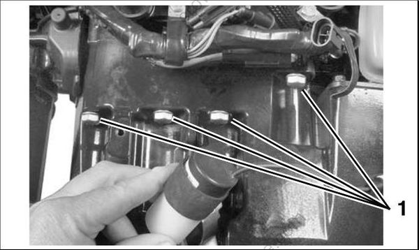
- Powerhead screws 004292
Tighten the eight powerhead screws to a torque of 18 to 20 ft. lbs. (24 to 27 N·m) in the sequence shown.
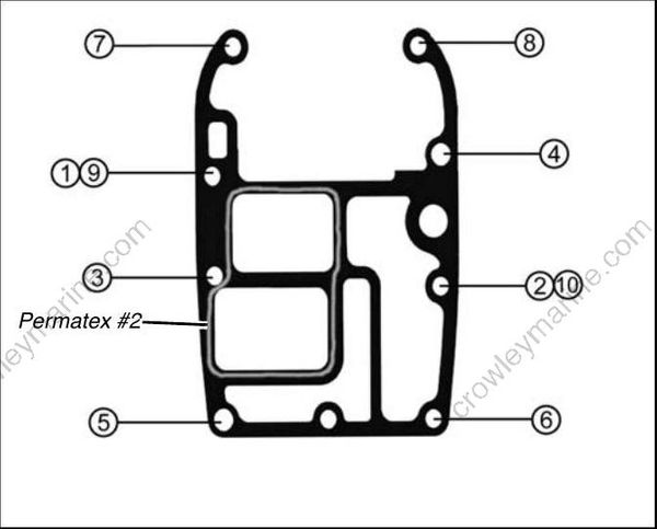
Large screw torque sequence, 1 – 10 002175
IMPORTANT: Retighten powerhead mounting screws after outboard has been run at full operating temperature and allowed to cool.
Place the shift rod in the shift rod lever. Install the retaining pin and washer. Tighten pin to a torque of 60 to 84 in. lbs. (7 to 9.5 N·m).
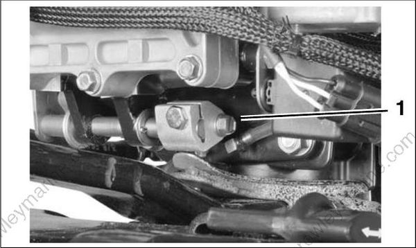
- Shift rod screw 002171
Check shift linkage adjustment. Refer to Shift Linkage Adjustment on p. 224.
IMPORTANT: Make sure the gearcase shifts completely into both forward and reverse and that propeller shaft spins freely in neutral.
Apply Nut Lock to threads of exhaust water valve screws and tighten to a torque of 60 to 84 in. lbs. (7 to 9.5 N.m).
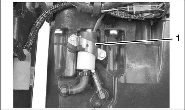
- Exhaust water valve 004293
Connect cooling water hoses to exhaust housing.
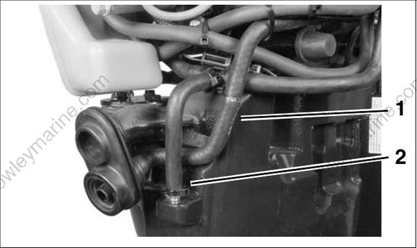
- Overboard indicator hose
- Drain hose
004298
Connect the power trim connectors and exhaust water valve connector (60, 65). Secure cables in clamps.
ROPE START MODELS
Install throttle cable and tiller shift rod.
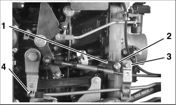
- Cable anchor
- Anchor screw
- Cable retainer
- Shift rod retainer
006526m
Refer to Throttle Cable Adjustment on p. 273, or Throttle Cable Adjustment on p. 284.
Install recoil starter ratchet and housing on outboard. Refer to RECOIL STARTER INSTALLA
TION on p. 371.
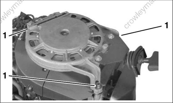
- Starter housing screws (3) 002515
Install the lower engine covers. Refer to LOWER COVER SERVICE on p. 54.
Powerhead Mounting – 3-Cylinder Models
Apply Permatex No. 2 to both sides of a new base gasket around the exhaust port only. Install gasket on adapter. To ensure proper sealing, mating sur faces must be clean and dry.
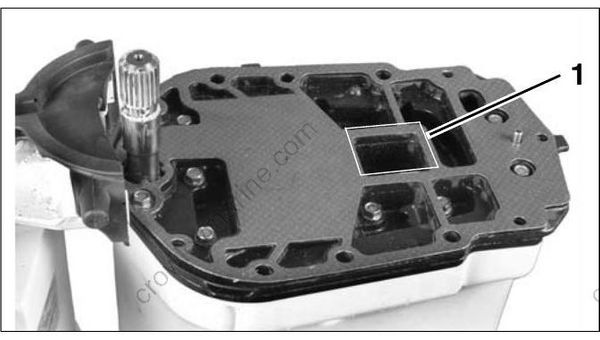
- Apply Permatex No. 2 here 002164
Coat the driveshaft splines with Moly Lube Do not apply lubricant to end of driveshaft.
Use Lifting Fixture, P/N 396748, and hoist to slowly lower powerhead onto exhaust housing. Guide into position over alignment pin at rear of exhaust housing. If necessary, rotate flywheel in a clockwise direction to align crankshaft and drive shaft splines.
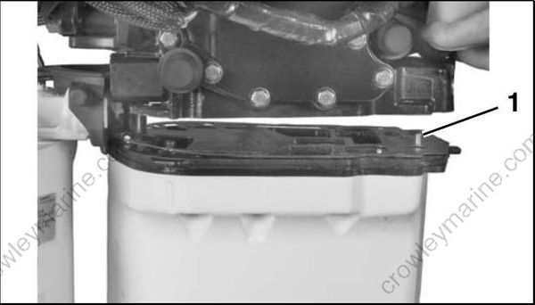
- Alignment pin 002162
Apply Triple-Guard grease to the threads, and Gasket Sealing Compound to the shank of the powerhead screws.
Apply Triple-Guard grease to upper mount screw threads.
Loosely install all powerhead screws and upper mount screws before tightening.
• Tighten the six large powerhead screws to a torque of 18 to 20 ft. lbs. (24 to 27 N·m) in the sequence shown.
• Tighten the five small powerhead screws to a torque of 60 to 84 in. lbs. (7 to 9.5 N·m).
• Tighten the upper mount screws to a torque of 110 to 130 ft. lbs. (149 to 176 N·m). Make sure that screw heads are tight against steering arm
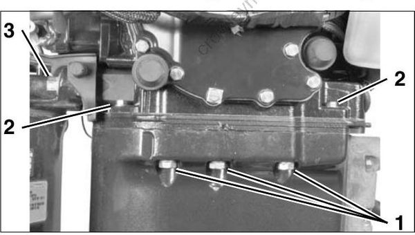
- Large powerhead screws
- Small powerhead screws
- Upper mount screws
002153
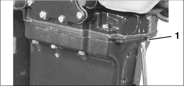
- Rear small powerhead screw 002160
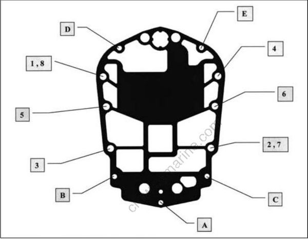
Large screw torque sequence, 1–8
Small screw torque sequence, A–E
002167
IMPORTANT: Retighten powerhead mounting screws after outboard has been run at full operating temperature and allowed to cool.
Apply Gasket Sealing Compound to exhaust relief muffler gasket and retaining screws. Install muffler and tighten screws to a torque of 60 to 84 in. lbs. (7 to 9.5 N·m).
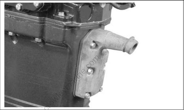
002163
Place the shift rod in the shift rod lever. Install the retaining pin and washer. Tighten pin to a torque of 60 to 84 in. lbs. (7 to 9.5 N·m).
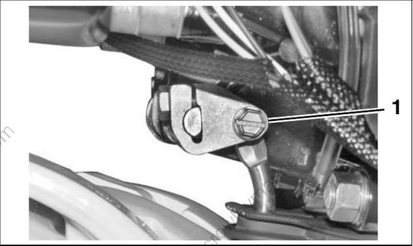
- Shift rod screw 002013
Check shift linkage adjustment. Refer to Shift Linkage Installation on p. 216.
IMPORTANT: Make sure the gearcase shifts solidly into both forward and reverse and that propeller shaft spins freely in neutral.
Connect the power trim connectors.
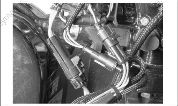
002152
Install the lower engine covers. Refer to LOWERCOVER SERVICE on p. 54.
Shift Linkage Adjustment
Adjust shift linkage as follows:
• Loosen adjustment screws on shift lever.
• Be sure that ball is centered in detent assembly.
• Adjust shift lever so that the screw hole in shift rod lever lines up with the hole in the gearcase shift rod when gearcase is in neutral.
• When correctly adjusted, the shift lever will be parallel with the vertical line of the outboard, and the distance between the shift lever pin and the center of the shift cable trunnion pocket should be approximately 7 in. (17.8 cm)
IMPORTANT: The shift rod height is the most critical of these adjustments and should not be moved during this procedure. Refer to SHIFT ROD ADJUSTMENT on p. 296, or SHIFT ROD ADJUSTMENT on p. 319
• Tighten adjustment screws to 60 to 84 in. lbs. (7 to 9.5 N·m).
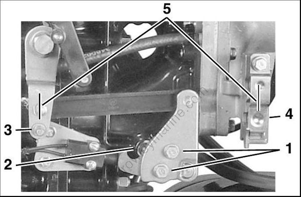
- Adjustment screws
- Shift detent assembly
- Shift lever pin
- Trunnion pocket
- 7 inch dimension
002125
Final Adjustments
After installing a new or rebuilt powerhead, perform the following procedures before returning outboard to service:
• Adjust timing pointer.
• Index all spark plugs. Refer to Spark Plug Indexing on p. 46.
• Use Evinrude Diagnostics software to start powerhead break-in oiling. Refer to Powerhead Break-In on p. 71.
• Use Evinrude Diagnostics software to set TPS calibration. Refer to TPS Calibration on p. 118.
• Use Evinrude Diagnostics software to make sure engine management software version and revision are current. Update as required.
• Prime fuel system.
• Prime oiling system. Refer to Oil Supply Priming on p. 169.
• Use Evinrude Diagnostics software to check engine timing. Refer to TIMING ADJUSTMENTS on p. 117.
• Run outboard and check for water, fuel, or oil leaks.
• Make sure engine reaches correct operating temperature and does not overheat